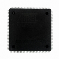
AT32AP7001-ALUT Atmel, AT32AP7001-ALUT Datasheet - Page 740

AT32AP7001-ALUT
Manufacturer Part Number
AT32AP7001-ALUT
Description
IC MCU 32BIT AVR32 208-LQFP
Manufacturer
Atmel
Series
AVR®32 AP7r
Specifications of AT32AP7001-ALUT
Core Processor
AVR
Core Size
32-Bit
Speed
150MHz
Connectivity
EBI/EMI, I²C, MMC, PS2, SPI, SSC, UART/USART, USB
Peripherals
AC'97, DMA, I²C, POR, PWM, WDT
Number Of I /o
90
Program Memory Type
ROMless
Ram Size
32K x 8
Voltage - Supply (vcc/vdd)
1.65 V ~ 1.95 V
Data Converters
D/A 2x16b
Oscillator Type
Internal
Operating Temperature
-40°C ~ 85°C
Package / Case
208-LQFP
Data Bus Width
32 bit
Data Ram Size
32 KB
Interface Type
EBI, ISI, MCI, PS2, SPI, TWI, USB
Maximum Clock Frequency
150 MHz
Number Of Programmable I/os
90
Number Of Timers
3
Maximum Operating Temperature
+ 85 C
Mounting Style
SMD/SMT
Minimum Operating Temperature
- 40 C
On-chip Dac
16 bit, 1 Channel
Package
208PQFP
Device Core
AVR32
Family Name
AT32
Maximum Speed
150 MHz
Operating Supply Voltage
1.8 V
For Use With
ATAVRONEKIT - KIT AVR/AVR32 DEBUGGER/PROGRMMRATNGW100 - KIT AVR32 NETWORK GATEWAYATSTK1000 - KIT STARTER FOR AVR32AP7000
Lead Free Status / RoHS Status
Lead free / RoHS Compliant
Eeprom Size
-
Program Memory Size
-
Lead Free Status / Rohs Status
Details
Available stocks
Company
Part Number
Manufacturer
Quantity
Price
Company:
Part Number:
AT32AP7001-ALUT
Manufacturer:
EVERLIGHT
Quantity:
12 000
- Current page: 740 of 829
- Download datasheet (12Mb)
35.3
Figure 35-2. Image Sensor Interface Block Diagram
35.4
35.4.1
35.4.2
32015G–AVR32–09/09
Hsync/Len
Vsync/Fen
RGB
YCbCr 4:2:2
CMOS
sensor
Pixel input
up to 12 bit
CMOS
sensor
pixel clock
input
8:8:8
5:6:5
Block Diagram
Product Dependencies
I/O Lines
Power Management
Decoder(SAV/EAV)
Embedded Timing
Timing Signals
Pixel Sampling
Frame Rate
CCIR-656
Interface
Module
Figure 35-1. ISI Connection Example
The pins used for interfacing the compliant external devices may be multiplexed with PIO lines.
The programmer must first program the PIO controllers to assign the ISI pins to their peripheral
functions.
The ISI clock is generated by the Power Manager. Before using the ISI, the programmer must
ensure that the ISIclock is enabled in the Power Manager.
In the ISI description, Master Clock (MCK) is the clock of the peripheral bus to which the ISI is
connected.
codec_on
Clipping + Color
Clipping + Color
YCC to RGB
Conversion
RGB to YCC
Conversion
Controller
Interrupt
Camera
Image Sensor
data[11..0]
VSYNC
HSYNC
2-D Image
PCLK
From
Rx buffers
Scaler
CLK
Camera
Interrupt Request Line
Formatter
Formatter
Packed
Pixel
Clock Domain
Pixel
Rx Direct
Rx Direct
Capture
Display
FIFO
FIFO
PB
Clock Domain
HSB
Clock Domain
ISI_DATA[11..0]
ISI_MCK
ISI_PCK
ISI_VSYNC
ISI_HSYNC
Image Sensor Interface
Registers
Config
Arbiter
Video
Core
AT32AP7001
Interface
Interface
Camera
Support
Master
Scatter
HSB
Mode
PB
740
Related parts for AT32AP7001-ALUT
Image
Part Number
Description
Manufacturer
Datasheet
Request
R

Part Number:
Description:
DEV KIT FOR AVR/AVR32
Manufacturer:
Atmel
Datasheet:

Part Number:
Description:
INTERVAL AND WIPE/WASH WIPER CONTROL IC WITH DELAY
Manufacturer:
ATMEL Corporation
Datasheet:

Part Number:
Description:
Low-Voltage Voice-Switched IC for Hands-Free Operation
Manufacturer:
ATMEL Corporation
Datasheet:

Part Number:
Description:
MONOLITHIC INTEGRATED FEATUREPHONE CIRCUIT
Manufacturer:
ATMEL Corporation
Datasheet:

Part Number:
Description:
AM-FM Receiver IC U4255BM-M
Manufacturer:
ATMEL Corporation
Datasheet:

Part Number:
Description:
Monolithic Integrated Feature Phone Circuit
Manufacturer:
ATMEL Corporation
Datasheet:

Part Number:
Description:
Multistandard Video-IF and Quasi Parallel Sound Processing
Manufacturer:
ATMEL Corporation
Datasheet:

Part Number:
Description:
High-performance EE PLD
Manufacturer:
ATMEL Corporation
Datasheet:

Part Number:
Description:
8-bit Flash Microcontroller
Manufacturer:
ATMEL Corporation
Datasheet:

Part Number:
Description:
2-Wire Serial EEPROM
Manufacturer:
ATMEL Corporation
Datasheet:


