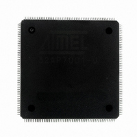
AT32AP7001-ALUT Atmel, AT32AP7001-ALUT Datasheet - Page 162

AT32AP7001-ALUT
Manufacturer Part Number
AT32AP7001-ALUT
Description
IC MCU 32BIT AVR32 208-LQFP
Manufacturer
Atmel
Series
AVR®32 AP7r
Specifications of AT32AP7001-ALUT
Core Processor
AVR
Core Size
32-Bit
Speed
150MHz
Connectivity
EBI/EMI, I²C, MMC, PS2, SPI, SSC, UART/USART, USB
Peripherals
AC'97, DMA, I²C, POR, PWM, WDT
Number Of I /o
90
Program Memory Type
ROMless
Ram Size
32K x 8
Voltage - Supply (vcc/vdd)
1.65 V ~ 1.95 V
Data Converters
D/A 2x16b
Oscillator Type
Internal
Operating Temperature
-40°C ~ 85°C
Package / Case
208-LQFP
Data Bus Width
32 bit
Data Ram Size
32 KB
Interface Type
EBI, ISI, MCI, PS2, SPI, TWI, USB
Maximum Clock Frequency
150 MHz
Number Of Programmable I/os
90
Number Of Timers
3
Maximum Operating Temperature
+ 85 C
Mounting Style
SMD/SMT
Minimum Operating Temperature
- 40 C
On-chip Dac
16 bit, 1 Channel
Package
208PQFP
Device Core
AVR32
Family Name
AT32
Maximum Speed
150 MHz
Operating Supply Voltage
1.8 V
For Use With
ATAVRONEKIT - KIT AVR/AVR32 DEBUGGER/PROGRMMRATNGW100 - KIT AVR32 NETWORK GATEWAYATSTK1000 - KIT STARTER FOR AVR32AP7000
Lead Free Status / RoHS Status
Lead free / RoHS Compliant
Eeprom Size
-
Program Memory Size
-
Lead Free Status / Rohs Status
Details
Available stocks
Company
Part Number
Manufacturer
Quantity
Price
Company:
Part Number:
AT32AP7001-ALUT
Manufacturer:
EVERLIGHT
Quantity:
12 000
- Current page: 162 of 829
- Download datasheet (12Mb)
17.7.6
17.7.6.1
32015G–AVR32–09/09
CompactFlash Support
I/O Mode, Common Memory Mode, Attribute Memory Mode and True IDE Mode
The External Bus Interface integrates circuitry that interfaces to CompactFlash devices.
The CompactFlash logic is driven by the Static Memory Controller (SMC) on the NCS4 and/or
NCS5 address space. Programming the EBI_CS4A and/or EBI_CS5A bits in a HMATRIX_SFR
Register to the appropriate value enables this logic. For details on this register, refer to the
Peripherals Section. Access to an external CompactFlash device is then made by accessing the
address space reserved to NCS4 and/or NCS5 (i.e., between 0x04000 0000 and 0x07FF FFFF
for NCS4 and between 0x2000 0000 and 0x23FF FFFF for NCS5).
All CompactFlash modes (Attribute Memory, Common Memory, I/O and True IDE) are sup-
ported but the signals _IOIS16 (I/O and True IDE modes) and _ATA SEL (True IDE mode) are
not handled.
Within the NCS4 and/or NCS5 address space, the current transfer address is used to distinguish
I/O mode, common memory mode, attribute memory mode and True IDE mode.
The different modes are accessed through a specific memory mapping as illustrated on
17-3. A[23:21] bits of the transfer address are used to select the desired mode as described in
Table 17-5 on page
Figure 17-3. CompactFlash Memory Mapping
Note:
The A22 pin is used to drive the REG signal of the CompactFlash Device (except in True IDE
mode).
CF Address Space
163.
Offset 0x00E0 0000
Offset 0x00C0 0000
Offset 0x0080 0000
Offset 0x0040 0000
Offset 0x0000 0000
Common Memory Mode Space
True IDE Alternate Mode Space
Attribute Memory Mode Space
True IDE Mode Space
I/O Mode Space
AT32AP7001
Figure
162
Related parts for AT32AP7001-ALUT
Image
Part Number
Description
Manufacturer
Datasheet
Request
R

Part Number:
Description:
DEV KIT FOR AVR/AVR32
Manufacturer:
Atmel
Datasheet:

Part Number:
Description:
INTERVAL AND WIPE/WASH WIPER CONTROL IC WITH DELAY
Manufacturer:
ATMEL Corporation
Datasheet:

Part Number:
Description:
Low-Voltage Voice-Switched IC for Hands-Free Operation
Manufacturer:
ATMEL Corporation
Datasheet:

Part Number:
Description:
MONOLITHIC INTEGRATED FEATUREPHONE CIRCUIT
Manufacturer:
ATMEL Corporation
Datasheet:

Part Number:
Description:
AM-FM Receiver IC U4255BM-M
Manufacturer:
ATMEL Corporation
Datasheet:

Part Number:
Description:
Monolithic Integrated Feature Phone Circuit
Manufacturer:
ATMEL Corporation
Datasheet:

Part Number:
Description:
Multistandard Video-IF and Quasi Parallel Sound Processing
Manufacturer:
ATMEL Corporation
Datasheet:

Part Number:
Description:
High-performance EE PLD
Manufacturer:
ATMEL Corporation
Datasheet:

Part Number:
Description:
8-bit Flash Microcontroller
Manufacturer:
ATMEL Corporation
Datasheet:

Part Number:
Description:
2-Wire Serial EEPROM
Manufacturer:
ATMEL Corporation
Datasheet:


