HD64F36077GHV Renesas Electronics America, HD64F36077GHV Datasheet - Page 21
HD64F36077GHV
Manufacturer Part Number
HD64F36077GHV
Description
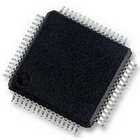
16BIT MCU FLASH 56K, SMD, LQFP64
Manufacturer
Renesas Electronics America
Datasheet
1.HD64F36077GHV.pdf
(524 pages)
Specifications of HD64F36077GHV
No. Of I/o's
47
Ram Memory Size
4KB
Cpu Speed
20MHz
No. Of Timers
4
Digital Ic Case Style
LQFP
Supply Voltage Range
4.5V
Core Size
16bit
Program Memory Size
56KB
Oscillator Type
External Only
Controller Family/series
H8/300H
Peripherals
ADC
Rohs Compliant
Yes
Lead Free Status / RoHS Status
Lead free / RoHS Compliant
Available stocks
Company
Part Number
Manufacturer
Quantity
Price
Company:

Part Number:
HD64F36077GHV
Manufacturer:
RENESAS
Quantity:
340
Part Number:
HD64F36077GHV
Manufacturer:
RENESAS/瑞萨
Quantity:
20 000


Section 11 Timer B1
Figure 11.1 Block Diagram of Timer B1.................................................................................... 171
Section 12 Timer V
Figure 12.1 Block Diagram of Timer V...................................................................................... 178
Figure 12.2 Increment Timing with Internal Clock .................................................................... 185
Figure 12.3 Increment Timing with External Clock ................................................................... 185
Figure 12.4 OVF Set Timing ...................................................................................................... 185
Figure 12.5 CMFA and CMFB Set Timing ................................................................................ 186
Figure 12.6 TMOV Output Timing ............................................................................................ 186
Figure 12.7 Clear Timing by Compare Match............................................................................ 186
Figure 12.8 Clear Timing by TMRIV Input ............................................................................... 187
Figure 12.9 Pulse Output Example ............................................................................................. 187
Figure 12.10 Example of Pulse Output Synchronized to TRGV Input....................................... 188
Figure 12.11 Contention between TCNTV Write and Clear ...................................................... 189
Figure 12.12 Contention between TCORA Write and Compare Match ..................................... 190
Figure 12.13 Internal Clock Switching and TCNTV Operation ................................................. 190
Section 13 Timer Z
Figure 13.1 Timer Z Block Diagram .......................................................................................... 193
Figure 13.2 Timer Z (Channel 0) Block Diagram ...................................................................... 194
Figure 13.3 Timer Z (Channel 1) Block Diagram ...................................................................... 195
Figure 13.4 Example of Outputs in Reset Synchronous PWM Mode
and Complementary PWM Mode............................................................................ 202
Figure 13.5 Accessing Operation of 16-Bit Register (between CPU and TCNT (16 bits)) ........ 214
Figure 13.6 Accessing Operation of 8-Bit Register (between CPU and TSTR (8 bits))............. 214
Figure 13.7 Example of Counter Operation Setting Procedure .................................................. 215
Figure 13.8 Free-Running Counter Operation ............................................................................ 216
Figure 13.9 Periodic Counter Operation..................................................................................... 217
Figure 13.10 Count Timing at Internal Clock Operation............................................................ 217
Figure 13.11 Count Timing at External Clock Operation (Both Edges Detected)...................... 218
Figure 13.12 Example of Setting Procedure for Waveform Output by Compare Match............ 219
Figure 13.13 Example of 0 Output/1 Output Operation ............................................................. 220
Figure 13.14 Example of Toggle Output Operation ................................................................... 220
Figure 13.15 Output Compare Timing........................................................................................ 221
Figure 13.16 Example of Input Capture Operation Setting Procedure ....................................... 222
Figure 13.17 Example of Input Capture Operation..................................................................... 223
Figure 13.18 Input Capture Signal Timing ................................................................................. 224
Figure 13.19 Example of Synchronous Operation Setting Procedure ........................................ 225
Figure 13.20 Example of Synchronous Operation...................................................................... 226
Figure 13.21 Example of PWM Mode Setting Procedure .......................................................... 227
Rev. 1.00 Sep. 16, 2005 Page xxi of xxx
Related parts for HD64F36077GHV
Image
Part Number
Description
Manufacturer
Datasheet
Request
R


Part Number:
Description:
KIT STARTER FOR M16C/29
Manufacturer:
Renesas Electronics America
Datasheet:

Part Number:
Description:
KIT STARTER FOR R8C/2D
Manufacturer:
Renesas Electronics America
Datasheet:

Part Number:
Description:
R0K33062P STARTER KIT
Manufacturer:
Renesas Electronics America
Datasheet:

Part Number:
Description:
KIT STARTER FOR R8C/23 E8A
Manufacturer:
Renesas Electronics America
Datasheet:

Part Number:
Description:
KIT STARTER FOR R8C/25
Manufacturer:
Renesas Electronics America
Datasheet:

Part Number:
Description:
KIT STARTER H8S2456 SHARPE DSPLY
Manufacturer:
Renesas Electronics America
Datasheet:

Part Number:
Description:
KIT STARTER FOR R8C38C
Manufacturer:
Renesas Electronics America
Datasheet:

Part Number:
Description:
KIT STARTER FOR R8C35C
Manufacturer:
Renesas Electronics America
Datasheet:

Part Number:
Description:
KIT STARTER FOR R8CL3AC+LCD APPS
Manufacturer:
Renesas Electronics America
Datasheet:
Part Number:
Description:
KIT STARTER FOR RX610
Manufacturer:
Renesas Electronics America
Datasheet:

Part Number:
Description:
KIT STARTER FOR R32C/118
Manufacturer:
Renesas Electronics America
Datasheet:

Part Number:
Description:
KIT DEV RSK-R8C/26-29
Manufacturer:
Renesas Electronics America
Datasheet:

Part Number:
Description:
KIT STARTER FOR SH7124
Manufacturer:
Renesas Electronics America
Datasheet:

Part Number:
Description:
KIT STARTER FOR H8SX/1622
Manufacturer:
Renesas Electronics America
Datasheet: