DSP56309EVM Freescale Semiconductor, DSP56309EVM Datasheet - Page 93
DSP56309EVM
Manufacturer Part Number
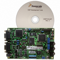
DSP56309EVM
Description
KIT EVALUATION FOR XC56309
Manufacturer
Freescale Semiconductor
Type
DSPr
Specifications of DSP56309EVM
Contents
Module Board, Installation Guide, Power Supply, Cable, Software and more
Description/function
Audio DSPs
Product
Audio Modules
For Use With/related Products
DSP56309
Lead Free Status / RoHS Status
Contains lead / RoHS non-compliant


Programming the Peripherals
When peripherals are programmed in a given application, a number of possible modes and
options are available for use. Chapters 6 through 9 describe in detail the possible modes and
configurations for peripheral registers and ports. This chapter presents general guidelines for
initializing the peripherals. These guidelines include a description of how the control registers are
mapped in the DSP56309, data transfer methods that are available when the various peripherals
are used, and information on General-Purpose Input/Output (GPIO) configuration.
5.1 Peripheral Initialization Steps
Each peripheral has its own initialization process. However, all four peripherals share some
common steps, which follow:
Note:
For detailed initialization procedures unique to each peripheral device, consult the initialization
section in the specific peripheral device chapter.
5.2 Mapping the Control Registers
The I/O peripherals are controlled through registers mapped to the top 128 words of X-data
memory ($FFFF80–$FFFFFF). Referred to as the internal I/O space, the control registers are
accessed by move (MOVE, MOVEP) instructions and bit-oriented instructions (BCHG, BCLR,
BSET, BTST, BRCLR, BRSET, BSCLR, BSSET, JCLR, JSET, JSCLR, and JSSET). The
Freescale Semiconductor
1.
2.
1.
2.
Determine the Register values to be programmed, using the following steps:
a.
b.
c.
Make sure the peripheral is in individual reset state or disabled.
Configure the registers by writing the predetermined values from step 1 into the
appropriate register locations.
Enable the peripheral. Once the peripheral is enabled, it operates according the
programmed modes determined in step 1.
Peripheral registers should not be modified while the peripheral is active.
Find the peripheral register descriptions in the manual.
Choose the appropriate modes to configure for a given application.
Determine the bit settings for programming those modes.
DSP56309 User’s Manual, Rev. 1
5
5-1
Related parts for DSP56309EVM
Image
Part Number
Description
Manufacturer
Datasheet
Request
R

Part Number:
Description:
Manufacturer:
Freescale Semiconductor, Inc
Datasheet:
Part Number:
Description:
Manufacturer:
Freescale Semiconductor, Inc
Datasheet:
Part Number:
Description:
Manufacturer:
Freescale Semiconductor, Inc
Datasheet:
Part Number:
Description:
Manufacturer:
Freescale Semiconductor, Inc
Datasheet:
Part Number:
Description:
Manufacturer:
Freescale Semiconductor, Inc
Datasheet:
Part Number:
Description:
Manufacturer:
Freescale Semiconductor, Inc
Datasheet:
Part Number:
Description:
Manufacturer:
Freescale Semiconductor, Inc
Datasheet:
Part Number:
Description:
Manufacturer:
Freescale Semiconductor, Inc
Datasheet:
Part Number:
Description:
Manufacturer:
Freescale Semiconductor, Inc
Datasheet:
Part Number:
Description:
Manufacturer:
Freescale Semiconductor, Inc
Datasheet:
Part Number:
Description:
Manufacturer:
Freescale Semiconductor, Inc
Datasheet:
Part Number:
Description:
Manufacturer:
Freescale Semiconductor, Inc
Datasheet:
Part Number:
Description:
Manufacturer:
Freescale Semiconductor, Inc
Datasheet:
Part Number:
Description:
Manufacturer:
Freescale Semiconductor, Inc
Datasheet:
Part Number:
Description:
Manufacturer:
Freescale Semiconductor, Inc
Datasheet: