DSP56309EVM Freescale Semiconductor, DSP56309EVM Datasheet - Page 65
DSP56309EVM
Manufacturer Part Number
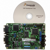
DSP56309EVM
Description
KIT EVALUATION FOR XC56309
Manufacturer
Freescale Semiconductor
Type
DSPr
Specifications of DSP56309EVM
Contents
Module Board, Installation Guide, Power Supply, Cable, Software and more
Description/function
Audio DSPs
Product
Audio Modules
For Use With/related Products
DSP56309
Lead Free Status / RoHS Status
Contains lead / RoHS non-compliant


4.3.1 Status Register (SR)
The Status Register (SR) (Figure 4-1) is a 24-bit register that indicates the current system state of
the processor and the results of previous arithmetic computations. The SR is pushed onto the
system stack when program looping is initialized or a jsr is performed, including long interrupts.
The SR consists of the following three special-purpose 8-bit control registers:
Freescale Semiconductor
Reset:
CP[1–0] RM SM CE
23
1
Extended Mode Register (EMR)
Reserved bit. Read as zero; write to zero for future compatibility
22
1
Extended Mode Register (EMR) (SR[23–16]) and Mode Register (MR) (SR[15–8]).
These special-purpose registers define the current system state of the processor. The bits
in both registers are affected by hardware reset, exception processing, enddo (end current
do loop) instructions, rti (return from interrupt) instructions, and trap instructions. In
addition, the EMR bits are affected by instructions that specify SR as their destination (for
example, do forever instructions, brkcc instructions, and movec). During hardware reset,
all EMR bits are cleared. The MR register bits are affected by do instructions, and
instructions that directly reference the MR (for example, andi, ori, or instructions, such as
movec, that specify SR as the destination). During processor reset, the interrupt mask bits
are set and all other bits are cleared.
Condition Code Register (CCR) (SR[7–0]). Defines the results of previous arithmetic
computations. The CCR bits are affected by Data Arithmetic Logic Unit (Data ALU)
operations, parallel move operations, instructions that directly reference the CCR (for
example, ori and andi), and instructions that specify SR as a destination (for example,
movec). Parallel move operations affect only the S and L bits of the CCR. During
processor reset, all CCR bits are cleared.
The definition of the three 8-bit registers within the SR is primarily for the purpose of
compatibility with other Freescale DSPs. Bit definitions in the following paragraphs
identify the bits within the SR and not within the subregister.
21
0
20
0
19
0
18
0
SA FV
17
0
16
0
Figure 4-1. Status Register (SR)
LF DM SC
15
0
DSP56309 User’s Manual, Rev. 1
14
0
Mode Register (MR)
13
0
12
0
11
S[1–0]
0
10
0
9
1
I[1–0]
8
1
Central Processor Unit (CPU) Registers
7
S
0
Condition Code Register (CCR)
6
L
0
5
E
0
U
4
0
N
3
0
2
Z
0
V
1
0
C
0
0
4-7
Related parts for DSP56309EVM
Image
Part Number
Description
Manufacturer
Datasheet
Request
R

Part Number:
Description:
Manufacturer:
Freescale Semiconductor, Inc
Datasheet:
Part Number:
Description:
Manufacturer:
Freescale Semiconductor, Inc
Datasheet:
Part Number:
Description:
Manufacturer:
Freescale Semiconductor, Inc
Datasheet:
Part Number:
Description:
Manufacturer:
Freescale Semiconductor, Inc
Datasheet:
Part Number:
Description:
Manufacturer:
Freescale Semiconductor, Inc
Datasheet:
Part Number:
Description:
Manufacturer:
Freescale Semiconductor, Inc
Datasheet:
Part Number:
Description:
Manufacturer:
Freescale Semiconductor, Inc
Datasheet:
Part Number:
Description:
Manufacturer:
Freescale Semiconductor, Inc
Datasheet:
Part Number:
Description:
Manufacturer:
Freescale Semiconductor, Inc
Datasheet:
Part Number:
Description:
Manufacturer:
Freescale Semiconductor, Inc
Datasheet:
Part Number:
Description:
Manufacturer:
Freescale Semiconductor, Inc
Datasheet:
Part Number:
Description:
Manufacturer:
Freescale Semiconductor, Inc
Datasheet:
Part Number:
Description:
Manufacturer:
Freescale Semiconductor, Inc
Datasheet:
Part Number:
Description:
Manufacturer:
Freescale Semiconductor, Inc
Datasheet:
Part Number:
Description:
Manufacturer:
Freescale Semiconductor, Inc
Datasheet: