DSP56309EVM Freescale Semiconductor, DSP56309EVM Datasheet - Page 111
DSP56309EVM
Manufacturer Part Number
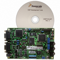
DSP56309EVM
Description
KIT EVALUATION FOR XC56309
Manufacturer
Freescale Semiconductor
Type
DSPr
Specifications of DSP56309EVM
Contents
Module Board, Installation Guide, Power Supply, Cable, Software and more
Description/function
Audio DSPs
Product
Audio Modules
For Use With/related Products
DSP56309
Lead Free Status / RoHS Status
Contains lead / RoHS non-compliant


6.5 Boot-up Using the HI08 Host Port
The DSP56300 core has eight bootstrap operating modes to start up after reset. As the processor
exits the Reset state the value at the external mode pins
MODD
Operating Mode Register (OMR). These bits determine the bootstrap operating mode. Modes C,
D, E and F use the HI08 host port to bootstrap the application code to the DSP. Table 6-7
describes these modes.
The bootstrap program is factory-programmed into an internal 192-word by 24-bit bootstrap
ROM at locations $FF0000–$FF00BF of P memory. This program can load program RAM
segment from the HI08 host port. When any of the modes in the preceding table are used, the core
begins executing the bootstrap program and configures the HI08 based on the OMR mode bits.
The bootstrap program then expects the following data sequence when the user program is
downloaded from the HI08:
Once the bootstrap program finishes loading the specified number of words, it jumps to the
specified starting address and executes the loaded program.
6.6 DSP Core Programming Model
The DSP56300 core treats the HI08 as a memory-mapped peripheral occupying eight 24-bit
words in X data memory space. The DSP can use the HI08 as a normal memory-mapped
peripheral, employing either standard polled or interrupt-driven programming techniques.
Separate transmit and receive data registers are double-buffered to allow the DSP and host
processor to transfer data efficiently at high speed. Direct memory mapping allows the
DSP56309 core to communicate with the HI08 registers using standard instructions and
Freescale Semiconductor
1.
2.
3.
Mode
C
D
E
F
/
IRQD
Three bytes (least significant byte first) indicating the number of 24-bit program words
to be loaded.
Three bytes (least significant byte first) indicating the 24-bit starting address in
P-memory to load the user's program.
The user program (three bytes, least significant byte first, for each program word).
are loaded into the Chip Operating Mode bits (MA, MB, MC and MD) of the
MODD
1
1
1
1
MODC
1
1
1
1
MODB
Table 6-7. HI08 Boot Modes
0
0
1
1
DSP56309 User’s Manual, Rev. 1
MODA
0
1
0
1
ISA/DSP5630x mode
HC11 non-multiplexed bus mode
8051 multiplexed bus mode
MC68302 bus mode
MODA
/
IRQA,
HI08 Bootstrap Description
MODB
Boot-up Using the HI08 Host Port
/
IRQB
,
MODC
/
IRQC
and
6-11
Related parts for DSP56309EVM
Image
Part Number
Description
Manufacturer
Datasheet
Request
R

Part Number:
Description:
Manufacturer:
Freescale Semiconductor, Inc
Datasheet:
Part Number:
Description:
Manufacturer:
Freescale Semiconductor, Inc
Datasheet:
Part Number:
Description:
Manufacturer:
Freescale Semiconductor, Inc
Datasheet:
Part Number:
Description:
Manufacturer:
Freescale Semiconductor, Inc
Datasheet:
Part Number:
Description:
Manufacturer:
Freescale Semiconductor, Inc
Datasheet:
Part Number:
Description:
Manufacturer:
Freescale Semiconductor, Inc
Datasheet:
Part Number:
Description:
Manufacturer:
Freescale Semiconductor, Inc
Datasheet:
Part Number:
Description:
Manufacturer:
Freescale Semiconductor, Inc
Datasheet:
Part Number:
Description:
Manufacturer:
Freescale Semiconductor, Inc
Datasheet:
Part Number:
Description:
Manufacturer:
Freescale Semiconductor, Inc
Datasheet:
Part Number:
Description:
Manufacturer:
Freescale Semiconductor, Inc
Datasheet:
Part Number:
Description:
Manufacturer:
Freescale Semiconductor, Inc
Datasheet:
Part Number:
Description:
Manufacturer:
Freescale Semiconductor, Inc
Datasheet:
Part Number:
Description:
Manufacturer:
Freescale Semiconductor, Inc
Datasheet:
Part Number:
Description:
Manufacturer:
Freescale Semiconductor, Inc
Datasheet: