DSP56309EVM Freescale Semiconductor, DSP56309EVM Datasheet - Page 13
DSP56309EVM
Manufacturer Part Number
DSP56309EVM
Description
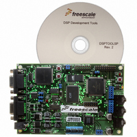
KIT EVALUATION FOR XC56309
Manufacturer
Freescale Semiconductor
Type
DSPr
Specifications of DSP56309EVM
Contents
Module Board, Installation Guide, Power Supply, Cable, Software and more
Description/function
Audio DSPs
Product
Audio Modules
For Use With/related Products
DSP56309
Lead Free Status / RoHS Status
Contains lead / RoHS non-compliant


1.3 Manual Revision History for Revision 1
Revision 1 is completely reorganized compared to Revision 0. This resulted in reordering of
information in most chapters and the deletion of the old Chapters 10 and 11 and Appendices B
and C. The old Appendix D became Appendix B. Other significant differences are listed in
Table 1-2.
Freescale Semiconductor
Modified signal definitions. Added note 5 pertaining to GND in Table 2-1.
Modified signal definitions. Added a note 4 pertaining to GND at the bottom of Figure
2-1. Removed overbars from HA10, HRW, AA0–AA3, and TMS.
Modified signal definitions. Changed the note at the end of Table 2-3.
Modified signal definitions. In Table 2-8, changed the State During Reset, Stop, or
Wait descriptions for the BR and BB signals.
Pins or signals that are asserted low (made active when pulled to ground) are indicated like
this:
— In text, they have an overbar: for example,
— In code examples, they have a tilde in front of their names. In Example 1-1, line 3
Sets of signals are indicated by the first and last signals in the set, for instance HAD[0–7].
“Input/Output” indicates a bidirectional signal. “Input or Output” indicates a signal that is
exclusively one or the other.
Code examples are displayed in a monospaced font, as shown in Example 1-1.
Hexadecimal values are indicated with a $ preceding the value, as follows: $FFFFFF is the
X memory address for the core interrupt priority register.
The word “reset” is used in four different contexts in this manual:
— the reset signal, written as
— the reset instruction, written as RESET
— the reset operating state, written as Reset
— the reset function, written as reset
BFSET#$0007,X:PCC; Configure:
refers to the
;
; ~SS0 as PC3 for GPIO
MISO0, MOSI0, SCK0 for SPI master
Table 1-2. Change History, Revision 0 to Revision 1
SS0
signal (shown as ~SS0).
Example 1-1. Sample Code Listing
Change
DSP56309 User’s Manual, Rev. 1
RESET
RESET
is asserted low.
Manual Revision History for Revision 1
line 1
line 2
line 3
Page 2-3
Page 2-4
Page 2-7
Pages 2-11 to
2-12
Page Number
Revision 0
Page 2-1
Page 2-2
Page 2-4
Pages 2-6 to
2-7
Page Number
Revision 1
1-3
Related parts for DSP56309EVM
Image
Part Number
Description
Manufacturer
Datasheet
Request
R

Part Number:
Description:
Manufacturer:
Freescale Semiconductor, Inc
Datasheet:
Part Number:
Description:
Manufacturer:
Freescale Semiconductor, Inc
Datasheet:
Part Number:
Description:
Manufacturer:
Freescale Semiconductor, Inc
Datasheet:
Part Number:
Description:
Manufacturer:
Freescale Semiconductor, Inc
Datasheet:
Part Number:
Description:
Manufacturer:
Freescale Semiconductor, Inc
Datasheet:
Part Number:
Description:
Manufacturer:
Freescale Semiconductor, Inc
Datasheet:
Part Number:
Description:
Manufacturer:
Freescale Semiconductor, Inc
Datasheet:
Part Number:
Description:
Manufacturer:
Freescale Semiconductor, Inc
Datasheet:
Part Number:
Description:
Manufacturer:
Freescale Semiconductor, Inc
Datasheet:
Part Number:
Description:
Manufacturer:
Freescale Semiconductor, Inc
Datasheet:
Part Number:
Description:
Manufacturer:
Freescale Semiconductor, Inc
Datasheet:
Part Number:
Description:
Manufacturer:
Freescale Semiconductor, Inc
Datasheet:
Part Number:
Description:
Manufacturer:
Freescale Semiconductor, Inc
Datasheet:
Part Number:
Description:
Manufacturer:
Freescale Semiconductor, Inc
Datasheet:
Part Number:
Description:
Manufacturer:
Freescale Semiconductor, Inc
Datasheet: