DSP56309EVM Freescale Semiconductor, DSP56309EVM Datasheet - Page 170
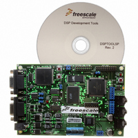
DSP56309EVM
Manufacturer Part Number
DSP56309EVM
Description
KIT EVALUATION FOR XC56309
Manufacturer
Freescale Semiconductor
Type
DSPr
Specifications of DSP56309EVM
Contents
Module Board, Installation Guide, Power Supply, Cable, Software and more
Description/function
Audio DSPs
Product
Audio Modules
For Use With/related Products
DSP56309
Lead Free Status / RoHS Status
Contains lead / RoHS non-compliant


Serial Communication Interface (SCI)
compatible with the MC68681 DUART, the M68HC11 SCI interface, and the Intel 8051 serial
interface.
8.1.1 Synchronous Mode
Synchronous mode (SCR[WD2–0]=000, Shift Register mode) handles serial-to-parallel and
parallel-to-serial conversions. In Synchronous mode, the clock is always common to the transmit
and receive shift registers. As a controller (synchronous master), the DSP puts out a clock on the
SCLK
RCM=0).
As a peripheral (synchronous slave), the DSP accepts an input clock from the
the slave mode, choose the external transmit and receive clocks (TCM and RCM=1). Since there
is no frame signal, if a clock is missed because of noise or any other reason, the receiver loses
synchronization with the data without any error signal being generated. You can detect an error
of this type with an error detecting protocol or with external circuitry such as a watchdog timer.
The simplest way to recover synchronization is to reset the SCI.
8.1.2 Asynchronous Mode
Asynchronous data uses a data format with embedded word sync, which allows an
unsynchronized data clock to be synchronized with the word if the clock rate and number of bits
per word is known. Thus, the clock can be generated by the receiver rather than requiring a
separate clock signal. The transmitter and receiver both use an internal clock that is 16 times the
data rate to allow the SCI to synchronize the data. The data format requires that each data byte
have an additional start bit and stop bit. Also, two of the word formats have a parity bit. The
Multidrop mode used when SCIs are on a common bus has an additional data type bit. The SCI
can operate in full-duplex or half-duplex modes since the transmitter and receiver are
independent.
8.1.3 Multidrop Mode
Multidrop is a special case of asynchronous data transfer. The key difference is that a protocol
allows networking transmitters and receivers on a single data-transmission line. Inter-processor
messages in a multidrop network typically begin with a destination address. All receivers check
for an address match at the start of each message. Receivers with no address match can ignore the
remainder of the message and use a wakeup mode to enable the receiver at the start of the next
message. Receivers with an address match can receive the message and optionally transmit an
acknowledgment to the sender. The particular message format and protocol used are determined
by the user’s software.
8-2
pin. To select master mode, choose the internal transmit and receive clocks (set TCM and
DSP56309 User’s Manual, Rev. 1
SCLK
Freescale Semiconductor
pin. To select
Related parts for DSP56309EVM
Image
Part Number
Description
Manufacturer
Datasheet
Request
R

Part Number:
Description:
Manufacturer:
Freescale Semiconductor, Inc
Datasheet:
Part Number:
Description:
Manufacturer:
Freescale Semiconductor, Inc
Datasheet:
Part Number:
Description:
Manufacturer:
Freescale Semiconductor, Inc
Datasheet:
Part Number:
Description:
Manufacturer:
Freescale Semiconductor, Inc
Datasheet:
Part Number:
Description:
Manufacturer:
Freescale Semiconductor, Inc
Datasheet:
Part Number:
Description:
Manufacturer:
Freescale Semiconductor, Inc
Datasheet:
Part Number:
Description:
Manufacturer:
Freescale Semiconductor, Inc
Datasheet:
Part Number:
Description:
Manufacturer:
Freescale Semiconductor, Inc
Datasheet:
Part Number:
Description:
Manufacturer:
Freescale Semiconductor, Inc
Datasheet:
Part Number:
Description:
Manufacturer:
Freescale Semiconductor, Inc
Datasheet:
Part Number:
Description:
Manufacturer:
Freescale Semiconductor, Inc
Datasheet:
Part Number:
Description:
Manufacturer:
Freescale Semiconductor, Inc
Datasheet:
Part Number:
Description:
Manufacturer:
Freescale Semiconductor, Inc
Datasheet:
Part Number:
Description:
Manufacturer:
Freescale Semiconductor, Inc
Datasheet:
Part Number:
Description:
Manufacturer:
Freescale Semiconductor, Inc
Datasheet: