DSP56309EVM Freescale Semiconductor, DSP56309EVM Datasheet - Page 212
DSP56309EVM
Manufacturer Part Number
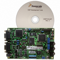
DSP56309EVM
Description
KIT EVALUATION FOR XC56309
Manufacturer
Freescale Semiconductor
Type
DSPr
Specifications of DSP56309EVM
Contents
Module Board, Installation Guide, Power Supply, Cable, Software and more
Description/function
Audio DSPs
Product
Audio Modules
For Use With/related Products
DSP56309
Lead Free Status / RoHS Status
Contains lead / RoHS non-compliant


Triple Timer Module
9.3.4.2 Watchdog Toggle (Mode 10)
In Mode 10, the timer toggles an external signal after a preset period. The
value of the INV bit.When the counter equals the value in the TCPR, TCSR[TCF] is set, and a
compare interrupt is generated if the TCSR[TCIE] bit is also set. If the TCSR[TRM] bit is set, the
counter loads with the TLR value on the next timer clock and the count resumes. Therefore, TRM
= 1 is not useful for watchdog functions. If the TCSR[TRM] bit is cleared, the counter continues
to increment on each subsequent timer clock. When a counter overflow occurs, the polarity of the
TIO
value while the TCSR[TE] bit is set. This process repeats until the timer is disabled. In Mode 10,
internal logic preserves the
the hardware
generated when the
9.3.4.3 Reserved Modes
Modes 8, 11, 12, 13, 14, and 15 are reserved.
9-20
TC3
1
output signal is inverted. The counter is reloaded whenever the TLR is written with a new
Mode 10 (internal clock): TRM = 0
TIO can connect to the RESET pin, internal hardware preserves the TIO value and
direction for an additional 2.5 clocks to ensure a reset of valid length.
N = write preload
M = write compare
TC2
Bit Settings
0
RESET
TE
Clock
(CLK/2 or prescale CLK)
TLR
TCPR
TCF (Compare Interrupt if TCIE = 1)
Counter (TCR)
TOF (Overflow Interrupt if TOIE = 1)
TIO pin (INV = 0)
TIO pin (INV = 1)
TC1
1
TIO
signal is asserted. This convention ensures that a valid reset signal is
signal resets the DSP56309.
TC0
float
float
0
TIO
Figure 9-19. Watchdog Toggle Mode
N
value and direction for an additional 2.5 internal clock cycles after
M
0
Mode
low
high
10
DSP56309 User’s Manual, Rev. 1
first event
N
Toggle
Name
N + 1
Mode Characteristics
TRM = 1 is not useful for watchdog function
M
Watchdog
Function
M + 1
TIO
Output
Freescale Semiconductor
signal is set to the
TIO
0
1
Internal
Clock
Related parts for DSP56309EVM
Image
Part Number
Description
Manufacturer
Datasheet
Request
R

Part Number:
Description:
Manufacturer:
Freescale Semiconductor, Inc
Datasheet:
Part Number:
Description:
Manufacturer:
Freescale Semiconductor, Inc
Datasheet:
Part Number:
Description:
Manufacturer:
Freescale Semiconductor, Inc
Datasheet:
Part Number:
Description:
Manufacturer:
Freescale Semiconductor, Inc
Datasheet:
Part Number:
Description:
Manufacturer:
Freescale Semiconductor, Inc
Datasheet:
Part Number:
Description:
Manufacturer:
Freescale Semiconductor, Inc
Datasheet:
Part Number:
Description:
Manufacturer:
Freescale Semiconductor, Inc
Datasheet:
Part Number:
Description:
Manufacturer:
Freescale Semiconductor, Inc
Datasheet:
Part Number:
Description:
Manufacturer:
Freescale Semiconductor, Inc
Datasheet:
Part Number:
Description:
Manufacturer:
Freescale Semiconductor, Inc
Datasheet:
Part Number:
Description:
Manufacturer:
Freescale Semiconductor, Inc
Datasheet:
Part Number:
Description:
Manufacturer:
Freescale Semiconductor, Inc
Datasheet:
Part Number:
Description:
Manufacturer:
Freescale Semiconductor, Inc
Datasheet:
Part Number:
Description:
Manufacturer:
Freescale Semiconductor, Inc
Datasheet:
Part Number:
Description:
Manufacturer:
Freescale Semiconductor, Inc
Datasheet: