C8051F930-TB Silicon Laboratories Inc, C8051F930-TB Datasheet - Page 157
C8051F930-TB
Manufacturer Part Number
C8051F930-TB
Description
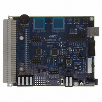
BOARD TARGET/PROTO W/C8051F930
Manufacturer
Silicon Laboratories Inc
Type
MCUr
Specifications of C8051F930-TB
Contents
Board
Processor To Be Evaluated
C8051F930
Processor Series
C8051F9xx
Data Bus Width
8 bit
Interface Type
I2C, UART, SPI
Maximum Operating Temperature
+ 85 C
Minimum Operating Temperature
- 40 C
Operating Supply Voltage
0.9 V to 3.6 V
Lead Free Status / RoHS Status
Lead free / RoHS Compliant
For Use With/related Products
C8051F930
Lead Free Status / Rohs Status
Lead free / RoHS Compliant
Other names
336-1472


14.1. Normal Mode
The MCU is fully functional in Normal Mode. Figure 14.1 shows the on-chip power distribution to various
peripherals. There are three supply voltages powering various sections of the chip: VBAT, VDD/DC+, and
the 1.8 V internal core supply. VREG0, PMU0 and the SmaRTClock are always powered directly from the
VBAT pin. All analog peripherals are directly powered from the VDD/DC+ pin, which is an output in one-cell
mode and an input in two-cell mode. All digital peripherals and the CIP-51 core are powered from the 1.8 V
internal core supply. The RAM is also powered from the core supply in Normal mode.
VBAT
SmaRTClock
PMU0
One-cell: 0.9 to 1.8 V
Two-cell: 1.8 to 3.6 V
Figure 14.1. C8051F93x-C8051F92x Power Distribution
Idle/Stop/Suspend
One-Cell Active/
One-Cell Sleep
DC0
Sleep
typical
1.9 V
Stop/Suspend
Active/Idle/
RAM
VDD/DC+
VREG0
Rev. 1.1
1.8 V
Note: VDD/DC+ must be > VBAT
C8051F93x-C8051F92x
One-cell or Two-cell: 1.8 to 3.6 V
M
U
A
X
Analog Peripherals
CIP-51
Digital Peripherals
Core
300 ksps
SENSOR
TEMP
VREF
10-bit
ADC
Timers
Flash
+
-
COMPARATORS
IREF0
VOLTAGE
SMBus
UART
SPI
+
-
GPIO
157
Related parts for C8051F930-TB
Image
Part Number
Description
Manufacturer
Datasheet
Request
R

Part Number:
Description:
SMD/C°/SINGLE-ENDED OUTPUT SILICON OSCILLATOR
Manufacturer:
Silicon Laboratories Inc
Part Number:
Description:
Manufacturer:
Silicon Laboratories Inc
Datasheet:
Part Number:
Description:
N/A N/A/SI4010 AES KEYFOB DEMO WITH LCD RX
Manufacturer:
Silicon Laboratories Inc
Datasheet:
Part Number:
Description:
N/A N/A/SI4010 SIMPLIFIED KEY FOB DEMO WITH LED RX
Manufacturer:
Silicon Laboratories Inc
Datasheet:
Part Number:
Description:
N/A/-40 TO 85 OC/EZLINK MODULE; F930/4432 HIGH BAND (REV E/B1)
Manufacturer:
Silicon Laboratories Inc
Part Number:
Description:
EZLink Module; F930/4432 Low Band (rev e/B1)
Manufacturer:
Silicon Laboratories Inc
Part Number:
Description:
I°/4460 10 DBM RADIO TEST CARD 434 MHZ
Manufacturer:
Silicon Laboratories Inc
Part Number:
Description:
I°/4461 14 DBM RADIO TEST CARD 868 MHZ
Manufacturer:
Silicon Laboratories Inc
Part Number:
Description:
I°/4463 20 DBM RFSWITCH RADIO TEST CARD 460 MHZ
Manufacturer:
Silicon Laboratories Inc
Part Number:
Description:
I°/4463 20 DBM RADIO TEST CARD 868 MHZ
Manufacturer:
Silicon Laboratories Inc
Part Number:
Description:
I°/4463 27 DBM RADIO TEST CARD 868 MHZ
Manufacturer:
Silicon Laboratories Inc
Part Number:
Description:
I°/4463 SKYWORKS 30 DBM RADIO TEST CARD 915 MHZ
Manufacturer:
Silicon Laboratories Inc
Part Number:
Description:
N/A N/A/-40 TO 85 OC/4463 RFMD 30 DBM RADIO TEST CARD 915 MHZ
Manufacturer:
Silicon Laboratories Inc
Part Number:
Description:
I°/4463 20 DBM RADIO TEST CARD 169 MHZ
Manufacturer:
Silicon Laboratories Inc