C8051F930-TB Silicon Laboratories Inc, C8051F930-TB Datasheet - Page 146
C8051F930-TB
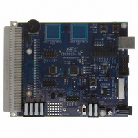
Manufacturer Part Number
C8051F930-TB
Description
BOARD TARGET/PROTO W/C8051F930
Manufacturer
Silicon Laboratories Inc
Type
MCUr
Specifications of C8051F930-TB
Contents
Board
Processor To Be Evaluated
C8051F930
Processor Series
C8051F9xx
Data Bus Width
8 bit
Interface Type
I2C, UART, SPI
Maximum Operating Temperature
+ 85 C
Minimum Operating Temperature
- 40 C
Operating Supply Voltage
0.9 V to 3.6 V
Lead Free Status / RoHS Status
Lead free / RoHS Compliant
For Use With/related Products
C8051F930
Lead Free Status / Rohs Status
Lead free / RoHS Compliant
Other names
336-1472


C8051F93x-C8051F92x
13.1.2. Flash Erase Procedure
The Flash memory is organized in 1024-byte pages. The erase operation applies to an entire page (setting
all bytes in the page to 0xFF). To erase an entire 1024-byte page, perform the following steps:
Steps 4–6 must be repeated for each 1024-byte page to be erased.
Notes:
13.1.3. Flash Write Procedure
A write to Flash memory can clear bits to logic 0 but cannot set them; only an erase operation can set bits
to logic 1 in Flash. A byte location to be programmed should be erased before a new value is written.
The recommended procedure for writing a single byte in Flash is as follows:
Steps 5–7 must be repeated for each byte to be written.
Notes:
13.2. Non-volatile Data Storage
The Flash memory can be used for non-volatile data storage as well as program code. This allows data
such as calibration coefficients to be calculated and stored at run time. Data is written using the MOVX
write instruction and read using the MOVC instruction. Note: MOVX read instructions always target XRAM.
146
1. Future 16 and 8 kB derivatives in this product family will use a 512-byte page size. To maintain code
2. Flash security settings may prevent erasure of some Flash pages, such as the reserved area and the page
3. 8-bit MOVX instructions cannot be used to erase or write to Flash memory at addresses higher than 0x00FF.
1. Future 16 and 8 kB derivatives in this product family will use a 512-byte page size. To maintain code
2. Flash security settings may prevent writes to some areas of Flash, such as the reserved area. For a summary
compatibility across the entire family, the erase procedure should be performed on each 512-byte section of
memory.
containing the lock bytes. For a summary of Flash security settings and restrictions affecting Flash erase
operations, please see Section “13.3. Security Options” on page 147.
compatibility across the entire family, the erase procedure should be performed on each 512-byte section of
memory.
of Flash security settings and restrictions affecting Flash write operations, please see Section “13.3. Security
Options” on page 147.
1. Save current interrupt state and disable interrupts.
2. Set the PSEE bit (register PSCTL).
3. Set the PSWE bit (register PSCTL).
4. Write the first key code to FLKEY: 0xA5.
5. Write the second key code to FLKEY: 0xF1.
6. Using the MOVX instruction, write a data byte to any location within the 1024-byte page to be
7. Clear the PSWE and PSEE bits.
8. Restore previous interrupt state.
1. Save current interrupt state and disable interrupts.
2. Ensure that the Flash byte has been erased (has a value of 0xFF).
3. Set the PSWE bit (register PSCTL).
4. Clear the PSEE bit (register PSCTL).
5. Write the first key code to FLKEY: 0xA5.
6. Write the second key code to FLKEY: 0xF1.
7. Using the MOVX instruction, write a single data byte to the desired location within the 1024-
8. Clear the PSWE bit.
9. Restore previous interrupt state.
erased.
byte sector.
Rev. 1.1
Related parts for C8051F930-TB
Image
Part Number
Description
Manufacturer
Datasheet
Request
R

Part Number:
Description:
SMD/C°/SINGLE-ENDED OUTPUT SILICON OSCILLATOR
Manufacturer:
Silicon Laboratories Inc
Part Number:
Description:
Manufacturer:
Silicon Laboratories Inc
Datasheet:
Part Number:
Description:
N/A N/A/SI4010 AES KEYFOB DEMO WITH LCD RX
Manufacturer:
Silicon Laboratories Inc
Datasheet:
Part Number:
Description:
N/A N/A/SI4010 SIMPLIFIED KEY FOB DEMO WITH LED RX
Manufacturer:
Silicon Laboratories Inc
Datasheet:
Part Number:
Description:
N/A/-40 TO 85 OC/EZLINK MODULE; F930/4432 HIGH BAND (REV E/B1)
Manufacturer:
Silicon Laboratories Inc
Part Number:
Description:
EZLink Module; F930/4432 Low Band (rev e/B1)
Manufacturer:
Silicon Laboratories Inc
Part Number:
Description:
I°/4460 10 DBM RADIO TEST CARD 434 MHZ
Manufacturer:
Silicon Laboratories Inc
Part Number:
Description:
I°/4461 14 DBM RADIO TEST CARD 868 MHZ
Manufacturer:
Silicon Laboratories Inc
Part Number:
Description:
I°/4463 20 DBM RFSWITCH RADIO TEST CARD 460 MHZ
Manufacturer:
Silicon Laboratories Inc
Part Number:
Description:
I°/4463 20 DBM RADIO TEST CARD 868 MHZ
Manufacturer:
Silicon Laboratories Inc
Part Number:
Description:
I°/4463 27 DBM RADIO TEST CARD 868 MHZ
Manufacturer:
Silicon Laboratories Inc
Part Number:
Description:
I°/4463 SKYWORKS 30 DBM RADIO TEST CARD 915 MHZ
Manufacturer:
Silicon Laboratories Inc
Part Number:
Description:
N/A N/A/-40 TO 85 OC/4463 RFMD 30 DBM RADIO TEST CARD 915 MHZ
Manufacturer:
Silicon Laboratories Inc
Part Number:
Description:
I°/4463 20 DBM RADIO TEST CARD 169 MHZ
Manufacturer:
Silicon Laboratories Inc