C8051T630DK Silicon Laboratories Inc, C8051T630DK Datasheet - Page 203
C8051T630DK
Manufacturer Part Number
C8051T630DK
Description
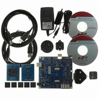
KIT DEV FOR C8051T630 FAMILY
Manufacturer
Silicon Laboratories Inc
Type
MCUr
Specifications of C8051T630DK
Contents
Board, daughter boards, power adapter, cables, documentation and software
Processor To Be Evaluated
C8051T63x
Interface Type
USB
Lead Free Status / RoHS Status
Lead free / RoHS Compliant
For Use With/related Products
C8051T630, T631, T632, T633, T634 and T635 MCUs
For Use With
336-1465 - BOARD SOCKET DAUGHTER 20-QFN
Lead Free Status / Rohs Status
Lead free / RoHS Compliant
Other names
336-1464


The 8-bit offset held in PCA0CPH2 is compared to the upper byte of the 16-bit PCA counter. This offset
value is the number of PCA0L overflows before a reset. Up to 256 PCA clocks may pass before the first
PCA0L overflow occurs, depending on the value of the PCA0L when the update is performed. The total off-
set is then given (in PCA clocks) by Equation 25.5, where PCA0L is the value of the PCA0L register at the
time of the update.
The WDT reset is generated when PCA0L overflows while there is a match between PCA0CPH2 and
PCA0H. Software may force a WDT reset by writing a 1 to the CCF2 flag (PCA0CN.2) while the WDT is
enabled.
25.4.2. Watchdog Timer Usage
To configure the WDT, perform the following tasks:
1. Disable the WDT by writing a 0 to the WDTE bit.
2. Select the desired PCA clock source (with the CPS2–CPS0 bits).
3. Load PCA0CPL2 with the desired WDT update offset value.
4. Configure the PCA Idle mode (set CIDL if the WDT should be suspended while the CPU is in Idle
5. Enable the WDT by setting the WDTE bit to 1.
6. Reset the WDT timer by writing to PCA0CPH2.
The PCA clock source and Idle mode select cannot be changed while the WDT is enabled. The watchdog
timer is enabled by setting the WDTE or WDLCK bits in the PCA0MD register. When WDLCK is set, the
WDT cannot be disabled until the next system reset. If WDLCK is not set, the WDT is disabled by clearing
the WDTE bit.
The WDT is enabled following any reset. The PCA0 counter clock defaults to the system clock divided by
12, PCA0L defaults to 0x00, and PCA0CPL2 defaults to 0x00. Using Equation 25.5, this results in a WDT
timeout interval of 256 PCA clock cycles, or 3072 system clock cycles. Table 25.3 lists some example tim-
eout intervals for typical system clocks.
mode).
Equation 25.5. Watchdog Timer Offset in PCA Clocks
Notes:
System Clock (Hz)
1. Assumes SYSCLK/12 as the PCA clock source, and a PCA0L value
2. Internal SYSCLK reset frequency = Internal Oscillator divided by 8.
Table 25.3. Watchdog Timer Timeout Intervals
Offset
24,500,000
24,500,000
24,500,000
of 0x00 at the update time.
3,062,500
3,062,500
3,062,500
32,000
32,000
32,000
=
2
2
2
256 PCA0CPL2
PCA0CPL2
Rev. 1.0
255
128
255
128
255
128
32
32
32
+
256 PCA0L
C8051T630/1/2/3/4/5
Timeout Interval (ms)
–
24576
12384
129.5
3168
32.1
16.2
33.1
257
4.1
1
203
Related parts for C8051T630DK
Image
Part Number
Description
Manufacturer
Datasheet
Request
R

Part Number:
Description:
SMD/C°/SINGLE-ENDED OUTPUT SILICON OSCILLATOR
Manufacturer:
Silicon Laboratories Inc
Part Number:
Description:
Manufacturer:
Silicon Laboratories Inc
Datasheet:
Part Number:
Description:
N/A N/A/SI4010 AES KEYFOB DEMO WITH LCD RX
Manufacturer:
Silicon Laboratories Inc
Datasheet:
Part Number:
Description:
N/A N/A/SI4010 SIMPLIFIED KEY FOB DEMO WITH LED RX
Manufacturer:
Silicon Laboratories Inc
Datasheet:
Part Number:
Description:
N/A/-40 TO 85 OC/EZLINK MODULE; F930/4432 HIGH BAND (REV E/B1)
Manufacturer:
Silicon Laboratories Inc
Part Number:
Description:
EZLink Module; F930/4432 Low Band (rev e/B1)
Manufacturer:
Silicon Laboratories Inc
Part Number:
Description:
I°/4460 10 DBM RADIO TEST CARD 434 MHZ
Manufacturer:
Silicon Laboratories Inc
Part Number:
Description:
I°/4461 14 DBM RADIO TEST CARD 868 MHZ
Manufacturer:
Silicon Laboratories Inc
Part Number:
Description:
I°/4463 20 DBM RFSWITCH RADIO TEST CARD 460 MHZ
Manufacturer:
Silicon Laboratories Inc
Part Number:
Description:
I°/4463 20 DBM RADIO TEST CARD 868 MHZ
Manufacturer:
Silicon Laboratories Inc
Part Number:
Description:
I°/4463 27 DBM RADIO TEST CARD 868 MHZ
Manufacturer:
Silicon Laboratories Inc
Part Number:
Description:
I°/4463 SKYWORKS 30 DBM RADIO TEST CARD 915 MHZ
Manufacturer:
Silicon Laboratories Inc
Part Number:
Description:
N/A N/A/-40 TO 85 OC/4463 RFMD 30 DBM RADIO TEST CARD 915 MHZ
Manufacturer:
Silicon Laboratories Inc
Part Number:
Description:
I°/4463 20 DBM RADIO TEST CARD 169 MHZ
Manufacturer:
Silicon Laboratories Inc