C8051T630DK Silicon Laboratories Inc, C8051T630DK Datasheet - Page 185
C8051T630DK
Manufacturer Part Number
C8051T630DK
Description
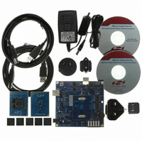
KIT DEV FOR C8051T630 FAMILY
Manufacturer
Silicon Laboratories Inc
Type
MCUr
Specifications of C8051T630DK
Contents
Board, daughter boards, power adapter, cables, documentation and software
Processor To Be Evaluated
C8051T63x
Interface Type
USB
Lead Free Status / RoHS Status
Lead free / RoHS Compliant
For Use With/related Products
C8051T630, T631, T632, T633, T634 and T635 MCUs
For Use With
336-1465 - BOARD SOCKET DAUGHTER 20-QFN
Lead Free Status / Rohs Status
Lead free / RoHS Compliant
Other names
336-1464


24.3. Timer 3
Timer 3 is a 16-bit timer formed by two 8-bit SFRs: TMR3L (low byte) and TMR3H (high byte). Timer 3 may
operate in 16-bit auto-reload mode or (split) 8-bit auto-reload mode. The T3SPLIT bit (TMR3CN.3) defines
the Timer 3 operation mode.
Timer 3 may be clocked by the system clock, the system clock divided by 12, the external oscillator source
divided by 8, or the internal low-frequency oscillator divided by 8. The external clock mode is ideal for real-
time clock (RTC) functionality, where the internal high-frequency oscillator drives the system clock while
Timer 3 is clocked by an external oscillator source. Note that the external oscillator source divided by 8 and
the LFO source divided by 8 are synchronized with the system clock when in all operating modes except
suspend. When the internal oscillator is placed in suspend mode, The external clock/8 signal or the LFO/8
output can directly drive the timer. This allows the use of an external clock or the LFO to wake up the
device from suspend mode. The timer will continue to run in suspend mode and count up. When the timer
overflow occurs, the device will wake from suspend mode, and begin executing code again. The timer
value may be set prior to entering suspend, to overflow in the desired amount of time (number of clocks) to
wake the device. If a wake-up source other than the timer wakes the device from suspend mode, it may
take up to three timer clocks before the timer registers can be read or written. During this time, the
STSYNC bit in register OSCICN will be set to 1, to indicate that it is not safe to read or write the timer reg-
isters.
Important Note: In internal LFO/8 mode, the divider for the internal LFO must be set to 1 for proper
functionality. The timer will not operate if the LFO divider is not set to 1.
24.3.1. 16-bit Timer with Auto-Reload
When T3SPLIT (TMR3CN.3) is zero, Timer 3 operates as a 16-bit timer with auto-reload. Timer 3 can be
clocked by SYSCLK, SYSCLK divided by 12, or the external oscillator clock source divided by 8. As the
16-bit timer register increments and overflows from 0xFFFF to 0x0000, the 16-bit value in the Timer 3
reload registers (TMR3RLH and TMR3RLL) is loaded into the Timer 3 register as shown in Figure 24.7,
and the Timer 3 High Byte Overflow Flag (TMR3CN.7) is set. If Timer 3 interrupts are enabled (if EIE1.7 is
set), an interrupt will be generated on each Timer 3 overflow. Additionally, if Timer 3 interrupts are enabled
and the TF3LEN bit is set (TMR3CN.5), an interrupt will be generated each time the lower 8 bits (TMR3L)
overflow from 0xFF to 0x00.
External Clock / 8
Internal LFO / 8
SYSCLK / 12
T3XCLK[1:0]
00
01
11
SYSCLK
Figure 24.7. Timer 3 16-Bit Mode Block Diagram
M
H
T
3
M
T
3
L
0
1
CKCON
T
M
H
2
T
M
2
L
TR3
M
T
1
M
T
0
S
C
A
1
S
C
A
0
TCLK
Rev. 1.0
TMR3RLL TMR3RLH
TMR3L
TMR3H
C8051T630/1/2/3/4/5
Reload
To ADC
T3XCLK1
T3XCLK0
TF3CEN
T3SPLIT
TF3LEN
TF3H
TF3L
TR3
Interrupt
185
Related parts for C8051T630DK
Image
Part Number
Description
Manufacturer
Datasheet
Request
R

Part Number:
Description:
SMD/C°/SINGLE-ENDED OUTPUT SILICON OSCILLATOR
Manufacturer:
Silicon Laboratories Inc
Part Number:
Description:
Manufacturer:
Silicon Laboratories Inc
Datasheet:
Part Number:
Description:
N/A N/A/SI4010 AES KEYFOB DEMO WITH LCD RX
Manufacturer:
Silicon Laboratories Inc
Datasheet:
Part Number:
Description:
N/A N/A/SI4010 SIMPLIFIED KEY FOB DEMO WITH LED RX
Manufacturer:
Silicon Laboratories Inc
Datasheet:
Part Number:
Description:
N/A/-40 TO 85 OC/EZLINK MODULE; F930/4432 HIGH BAND (REV E/B1)
Manufacturer:
Silicon Laboratories Inc
Part Number:
Description:
EZLink Module; F930/4432 Low Band (rev e/B1)
Manufacturer:
Silicon Laboratories Inc
Part Number:
Description:
I°/4460 10 DBM RADIO TEST CARD 434 MHZ
Manufacturer:
Silicon Laboratories Inc
Part Number:
Description:
I°/4461 14 DBM RADIO TEST CARD 868 MHZ
Manufacturer:
Silicon Laboratories Inc
Part Number:
Description:
I°/4463 20 DBM RFSWITCH RADIO TEST CARD 460 MHZ
Manufacturer:
Silicon Laboratories Inc
Part Number:
Description:
I°/4463 20 DBM RADIO TEST CARD 868 MHZ
Manufacturer:
Silicon Laboratories Inc
Part Number:
Description:
I°/4463 27 DBM RADIO TEST CARD 868 MHZ
Manufacturer:
Silicon Laboratories Inc
Part Number:
Description:
I°/4463 SKYWORKS 30 DBM RADIO TEST CARD 915 MHZ
Manufacturer:
Silicon Laboratories Inc
Part Number:
Description:
N/A N/A/-40 TO 85 OC/4463 RFMD 30 DBM RADIO TEST CARD 915 MHZ
Manufacturer:
Silicon Laboratories Inc
Part Number:
Description:
I°/4463 20 DBM RADIO TEST CARD 169 MHZ
Manufacturer:
Silicon Laboratories Inc