STEVAL-ISB005V1 STMicroelectronics, STEVAL-ISB005V1 Datasheet - Page 93
STEVAL-ISB005V1
Manufacturer Part Number
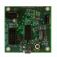
STEVAL-ISB005V1
Description
BOARD EVAL CHARGER ST7260/L6924D
Manufacturer
STMicroelectronics
Type
Battery Managementr
Specifications of STEVAL-ISB005V1
Main Purpose
Power Management, Battery Charger
Embedded
Yes, MCU, 8-Bit
Utilized Ic / Part
L6924, ST72F63BK6M1
Primary Attributes
1 Cell- Li-Ion / Li-Pol, 5 V (USB Input)
Secondary Attributes
Powered by Wall Adaptor Also, LED Status Indicators
Input Voltage
5 V
Product
Power Management Modules
Lead Free Status / RoHS Status
Lead free / RoHS Compliant
For Use With/related Products
L6924D, ST7260
Other names
497-8428
Available stocks
Company
Part Number
Manufacturer
Quantity
Price
Company:

Part Number:
STEVAL-ISB005V1
Manufacturer:
STMicroelectronics
Quantity:
1


ST7260xx
Note:
Note:
14.4.5
0: No error detected
1: Timeout, CRC, bit stuffing or nonstandard
framing error detected
Bit 3 = IOVR Interrupt overrun.
This bit is set when hardware tries to set ERR, or SOF before they have been cleared by
software.
0: No overrun detected
1: Overrun detected
Bit 2 = ESUSP End suspend mode.
This bit is set by hardware when, during suspend mode, activity is detected that wakes the
USB interface up from suspend mode.
This interrupt is serviced by a specific vector, in order to wake up the ST7 from HALT mode.
0: No End Suspend detected
1: End Suspend detected
Bit 1 = RESET USB reset.
This bit is set by hardware when the USB reset sequence is detected on the bus.
0: No USB reset signal detected
1: USB reset signal detected
The DADDR, EP0RA, EP0RB, EP1RA, EP1RB, EP2RA and EP2RB registers are reset by a
USB reset.
Bit 0 = SOF Start of frame.
This bit is set by hardware when a low-speed SOF indication (keep-alive strobe) is seen on
the USB bus. It is also issued at the end of a resume sequence.
0: No SOF signal detected
1: SOF signal detected
To avoid spurious clearing of some bits, it is recommended to clear them using a load
instruction where all bits which must not be altered are set, and all bits to be cleared are
reset. Avoid read-modify-write instructions like AND , XOR..
Interrupt mask register (IMR)
Bits 7:0 = These bits are mask bits for all interrupt condition bits included in the ISTR.
Whenever one of the IMR bits is set, if the corresponding ISTR bit is set, and the I bit in the
CC register is cleared, an interrupt request is generated. For an explanation of each bit,
please refer to the corresponding bit description in ISTR.
IMR
SUSPM
R/W
7
DOVRM
R/W
6
CTRM
R/W
5
ERRM
R/W
4
IOVRM
R/W
3
ESUSPM
R/W
2
Reset value:
USB interface (USB)
RESETM
R/W
1
0000 0000 (00h)
SOFM
R/W
0
93/139
Related parts for STEVAL-ISB005V1
Image
Part Number
Description
Manufacturer
Datasheet
Request
R

Part Number:
Description:
BOARD RGB CTR ST7,STP08C596MTR
Manufacturer:
STMicroelectronics
Datasheet:

Part Number:
Description:
Power Management IC Development Tools Full Speed USB to RS232 Bridge Demo
Manufacturer:
STMicroelectronics
Datasheet:
Part Number:
Description:
Power Management IC Development Tools 2.5W solar eval BRD USB SPV1040 LD39050
Manufacturer:
STMicroelectronics
Datasheet:

Part Number:
Description:
BOARD EVAL FOR MEMS SENSORS
Manufacturer:
STMicroelectronics
Datasheet:

Part Number:
Description:
KIT DEV STARTER ST10F276Z5
Manufacturer:
STMicroelectronics
Datasheet:

Part Number:
Description:
BOARD EVAL HDMI $ VIDEO SWITCH
Manufacturer:
STMicroelectronics
Datasheet:

Part Number:
Description:
BOARD DEMO ACCELEROMETER DIL24
Manufacturer:
STMicroelectronics
Datasheet:

Part Number:
Description:
BOARD STLM75/STDS75/ST72F651
Manufacturer:
STMicroelectronics
Datasheet:

Part Number:
Description:
EVAL BOARD 3AXIS MEMS ACCELLRMTR
Manufacturer:
STMicroelectronics
Datasheet:

Part Number:
Description:
BOARD EVAL 8BIT MICRO + TDE1708
Manufacturer:
STMicroelectronics
Datasheet:
Part Number:
Description:
STMicroelectronics [RIPPLE-CARRY BINARY COUNTER/DIVIDERS]
Manufacturer:
STMicroelectronics
Datasheet:
Part Number:
Description:
STMicroelectronics [LIQUID-CRYSTAL DISPLAY DRIVERS]
Manufacturer:
STMicroelectronics
Datasheet:
Part Number:
Description:
BOARD EVAL FOR MEMS SENSORS
Manufacturer:
STMicroelectronics
Datasheet: