STEVAL-ISB005V1 STMicroelectronics, STEVAL-ISB005V1 Datasheet - Page 79
STEVAL-ISB005V1
Manufacturer Part Number
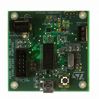
STEVAL-ISB005V1
Description
BOARD EVAL CHARGER ST7260/L6924D
Manufacturer
STMicroelectronics
Type
Battery Managementr
Specifications of STEVAL-ISB005V1
Main Purpose
Power Management, Battery Charger
Embedded
Yes, MCU, 8-Bit
Utilized Ic / Part
L6924, ST72F63BK6M1
Primary Attributes
1 Cell- Li-Ion / Li-Pol, 5 V (USB Input)
Secondary Attributes
Powered by Wall Adaptor Also, LED Status Indicators
Input Voltage
5 V
Product
Power Management Modules
Lead Free Status / RoHS Status
Lead free / RoHS Compliant
For Use With/related Products
L6924D, ST7260
Other names
497-8428
Available stocks
Company
Part Number
Manufacturer
Quantity
Price
Company:

Part Number:
STEVAL-ISB005V1
Manufacturer:
STMicroelectronics
Quantity:
1


ST7260xx
Note:
Note:
Parity control
Parity control (generation of parity bit in transmission and parity checking in reception) can
be enabled by setting the PCE bit in the SCICR1 register. Depending on the frame length
defined by the M bit, the possible SCI frame formats are as listed in
Table 35.
Legend: SB = Start Bit, STB = Stop Bit,
PB = Parity Bit
In case of wake up by an address mark, the MSB bit of the data is taken into account and
not the parity bit
Even parity: the parity bit is calculated to obtain an even number of “1s” inside the frame
made of the 7 or 8 LSB bits (depending on whether M is equal to 0 or 1) and the parity bit.
Ex: data=00110101; 4 bits set => parity bit will be 0 if even parity is selected (PS bit = 0).
Odd parity: the parity bit is calculated to obtain an odd number of “1s” inside the frame
made of the 7 or 8 LSB bits (depending on whether M is equal to 0 or 1) and the parity bit.
Ex: data=00110101; 4 bits set => parity bit will be 1 if odd parity is selected (PS bit = 1).
Transmission mode: If the PCE bit is set then the MSB bit of the data written in the data
register is not transmitted but is changed by the parity bit.
Reception mode: If the PCE bit is set then the interface checks if the received data byte
has an even number of “1s” if even parity is selected (PS=0) or an odd number of “1s” if odd
parity is selected (PS=1). If the parity check fails, the PE flag is set in the SCISR register
and an interrupt is generated if PIE is set in the SCICR1 register.
SCI clock tolerance
During reception, each bit is sampled 16 times. The majority of the 8th, 9th and 10th
samples is considered as the bit value. For a valid bit detection, all the three samples should
have the same value otherwise the noise flag (NF) is set. For example: if the 8th, 9th and
10th samples are 0, 1 and 1 respectively, then the bit value will be “1”, but the Noise Flag bit
is be set because the three samples values are not the same.
Consequently, the bit length must be long enough so that the 8th, 9th and 10th samples
have the desired bit value. This means the clock frequency should not vary more than 6/16
(37.5%) within one bit. The sampling clock is resynchronized at each start bit, so that when
receiving 10 bits (one start bit, 1 data byte, 1 stop bit), the clock deviation must not exceed
3.75%.
The internal sampling clock of the microcontroller samples the pin value on every falling
edge. Therefore, the internal sampling clock and the time the application expects the
sampling to take place may be out of sync. For example: If the baud rate is 15.625 kbaud (bit
length is 64 µs), then the 8th, 9th and 10th samples will be at 28 µs, 32 µs & 36 µs
respectively (the first sample starting ideally at 0µs). But if the falling edge of the internal
M bit
0
0
1
1
Frame formats
PCE bit
0
1
0
1
Serial communications interface (SCI)
| SB | 7-bit data | PB | STB |
| SB | 8-bit data PB | STB |
| SB | 9-bit data | STB |
| SB | 8 bit data | STB |
SCI frame
Table
35.
79/139
Related parts for STEVAL-ISB005V1
Image
Part Number
Description
Manufacturer
Datasheet
Request
R

Part Number:
Description:
BOARD RGB CTR ST7,STP08C596MTR
Manufacturer:
STMicroelectronics
Datasheet:

Part Number:
Description:
Power Management IC Development Tools Full Speed USB to RS232 Bridge Demo
Manufacturer:
STMicroelectronics
Datasheet:
Part Number:
Description:
Power Management IC Development Tools 2.5W solar eval BRD USB SPV1040 LD39050
Manufacturer:
STMicroelectronics
Datasheet:

Part Number:
Description:
BOARD EVAL FOR MEMS SENSORS
Manufacturer:
STMicroelectronics
Datasheet:

Part Number:
Description:
KIT DEV STARTER ST10F276Z5
Manufacturer:
STMicroelectronics
Datasheet:

Part Number:
Description:
BOARD EVAL HDMI $ VIDEO SWITCH
Manufacturer:
STMicroelectronics
Datasheet:

Part Number:
Description:
BOARD DEMO ACCELEROMETER DIL24
Manufacturer:
STMicroelectronics
Datasheet:

Part Number:
Description:
BOARD STLM75/STDS75/ST72F651
Manufacturer:
STMicroelectronics
Datasheet:

Part Number:
Description:
EVAL BOARD 3AXIS MEMS ACCELLRMTR
Manufacturer:
STMicroelectronics
Datasheet:

Part Number:
Description:
BOARD EVAL 8BIT MICRO + TDE1708
Manufacturer:
STMicroelectronics
Datasheet:
Part Number:
Description:
STMicroelectronics [RIPPLE-CARRY BINARY COUNTER/DIVIDERS]
Manufacturer:
STMicroelectronics
Datasheet:
Part Number:
Description:
STMicroelectronics [LIQUID-CRYSTAL DISPLAY DRIVERS]
Manufacturer:
STMicroelectronics
Datasheet:
Part Number:
Description:
BOARD EVAL FOR MEMS SENSORS
Manufacturer:
STMicroelectronics
Datasheet: