STEVAL-ISB005V1 STMicroelectronics, STEVAL-ISB005V1 Datasheet - Page 24
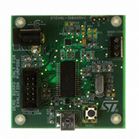
STEVAL-ISB005V1
Manufacturer Part Number
STEVAL-ISB005V1
Description
BOARD EVAL CHARGER ST7260/L6924D
Manufacturer
STMicroelectronics
Type
Battery Managementr
Specifications of STEVAL-ISB005V1
Main Purpose
Power Management, Battery Charger
Embedded
Yes, MCU, 8-Bit
Utilized Ic / Part
L6924, ST72F63BK6M1
Primary Attributes
1 Cell- Li-Ion / Li-Pol, 5 V (USB Input)
Secondary Attributes
Powered by Wall Adaptor Also, LED Status Indicators
Input Voltage
5 V
Product
Power Management Modules
Lead Free Status / RoHS Status
Lead free / RoHS Compliant
For Use With/related Products
L6924D, ST7260
Other names
497-8428
Available stocks
Company
Part Number
Manufacturer
Quantity
Price
Company:

Part Number:
STEVAL-ISB005V1
Manufacturer:
STMicroelectronics
Quantity:
1


Central processing unit (CPU)
6.3.5
Note:
24/139
Stack pointer register (SP)
The Stack Pointer is a 16-bit register which is always pointing to the next free location in the
stack. It is then decremented after data has been pushed onto the stack and incremented
before data is popped from the stack (see
Since the stack is 128 bytes deep, the 9 most significant bits are forced by hardware.
Following an MCU reset, or after a Reset Stack Pointer instruction (RSP), the Stack Pointer
contains its reset value (the SP7 to SP0 bits are set) which is the stack higher address.
The least significant byte of the Stack Pointer (called S) can be directly accessed by an LD
instruction.
When the lower limit is exceeded, the Stack Pointer wraps around to the stack upper limit,
without indicating the stack overflow. The previously stored information is then overwritten
and therefore lost. The stack also wraps in case of an underflow.
The stack is used to save the return address during a subroutine call and the CPU context
during an interrupt. The user may also directly manipulate the stack by means of the PUSH
and POP instructions. In the case of an interrupt, the PCL is stored at the first location
pointed to by the SP. Then the other registers are stored in the next locations as shown in
Figure
●
●
A subroutine call occupies two locations and an interrupt five locations in the stack area.
Figure 8.
SP
15
0
When an interrupt is received, the SP is decremented and the context is pushed on the
stack.
On return from interrupt, the SP is incremented and the context is popped from the
stack.
@ 0100h
@ 01FFh
SP
8.
14
0
subroutine
Stack Higher Address = 017Fh
Stack Lower Address = 0100h
Stack manipulation example
Call
13
0
PCH
PCL
12
0
SP
11
0
Interrupt
event
PCH
PCH
PCL
PCL
CC
A
X
10
0
SP
9
0
Push Y
PCH
PCH
PCL
PCL
CC
8
1
Figure
Y
A
X
SP
7
0
8).
R/W R/W R/W R/W R/W R/W R/W
SP6 SP5 SP4 SP3 SP2 SP1 SP0
6
Pop Y
PCH
PCH
PCL
PCL
CC
A
X
5
SP
4
IRET
PCH
PCL
3
Reset value: 01 7Fh
SP
2
or RSP
ST7260xx
RET
1
0
Related parts for STEVAL-ISB005V1
Image
Part Number
Description
Manufacturer
Datasheet
Request
R

Part Number:
Description:
BOARD RGB CTR ST7,STP08C596MTR
Manufacturer:
STMicroelectronics
Datasheet:

Part Number:
Description:
Power Management IC Development Tools Full Speed USB to RS232 Bridge Demo
Manufacturer:
STMicroelectronics
Datasheet:
Part Number:
Description:
Power Management IC Development Tools 2.5W solar eval BRD USB SPV1040 LD39050
Manufacturer:
STMicroelectronics
Datasheet:

Part Number:
Description:
BOARD EVAL FOR MEMS SENSORS
Manufacturer:
STMicroelectronics
Datasheet:

Part Number:
Description:
KIT DEV STARTER ST10F276Z5
Manufacturer:
STMicroelectronics
Datasheet:

Part Number:
Description:
BOARD EVAL HDMI $ VIDEO SWITCH
Manufacturer:
STMicroelectronics
Datasheet:

Part Number:
Description:
BOARD DEMO ACCELEROMETER DIL24
Manufacturer:
STMicroelectronics
Datasheet:

Part Number:
Description:
BOARD STLM75/STDS75/ST72F651
Manufacturer:
STMicroelectronics
Datasheet:

Part Number:
Description:
EVAL BOARD 3AXIS MEMS ACCELLRMTR
Manufacturer:
STMicroelectronics
Datasheet:

Part Number:
Description:
BOARD EVAL 8BIT MICRO + TDE1708
Manufacturer:
STMicroelectronics
Datasheet:
Part Number:
Description:
STMicroelectronics [RIPPLE-CARRY BINARY COUNTER/DIVIDERS]
Manufacturer:
STMicroelectronics
Datasheet:
Part Number:
Description:
STMicroelectronics [LIQUID-CRYSTAL DISPLAY DRIVERS]
Manufacturer:
STMicroelectronics
Datasheet:
Part Number:
Description:
BOARD EVAL FOR MEMS SENSORS
Manufacturer:
STMicroelectronics
Datasheet: