STEVAL-ISB005V1 STMicroelectronics, STEVAL-ISB005V1 Datasheet - Page 92
STEVAL-ISB005V1
Manufacturer Part Number
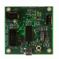
STEVAL-ISB005V1
Description
BOARD EVAL CHARGER ST7260/L6924D
Manufacturer
STMicroelectronics
Type
Battery Managementr
Specifications of STEVAL-ISB005V1
Main Purpose
Power Management, Battery Charger
Embedded
Yes, MCU, 8-Bit
Utilized Ic / Part
L6924, ST72F63BK6M1
Primary Attributes
1 Cell- Li-Ion / Li-Pol, 5 V (USB Input)
Secondary Attributes
Powered by Wall Adaptor Also, LED Status Indicators
Input Voltage
5 V
Product
Power Management Modules
Lead Free Status / RoHS Status
Lead free / RoHS Compliant
For Use With/related Products
L6924D, ST7260
Other names
497-8428
Available stocks
Company
Part Number
Manufacturer
Quantity
Price
Company:

Part Number:
STEVAL-ISB005V1
Manufacturer:
STMicroelectronics
Quantity:
1


USB interface (USB)
Note:
14.4.4
Note:
Note:
92/139
Bit 2 = RX_SEZ Received single-ended zero
This bit indicates the status of the RX_SEZ transceiver output.
0: No SE0 (single-ended zero) state
1: USB lines are in SE0 (single-ended zero) state
Bit 1 = RXD Received data
0: No K-state
1: USB lines are in K-state
This bit indicates the status of the RXD transceiver output (differential receiver output).
If the environment is noisy, the RX_SEZ and RXD bits can be used to secure the
application. By interpreting the status, software can distinguish a valid End Suspend event
from a spurious wake-up due to noise on the external USB line. A valid End Suspend is
followed by a Resume or Reset sequence. A Resume is indicated by RXD=1, a Reset is
indicated by RX_SEZ=1.
Bit 0 = Reserved. Forced by hardware to 0.
Interrupt status register (ISTR)
When an interrupt occurs these bits are set by hardware. Software must read them to
determine the interrupt type and clear them after servicing.
These bits cannot be set by software.
Bit 7 = SUSP Suspend mode request.
This bit is set by hardware when a constant idle state is present on the bus line for more
than 3 ms, indicating a suspend mode request from the USB bus. The suspend request
check is active immediately after each USB reset event and its disabled by hardware when
suspend mode is forced (FSUSP bit of CTLR register) until the end of resume sequence.
Bit 6 = DOVR DMA over/underrun.
This bit is set by hardware if the ST7 processor can’t answer a DMA request in time.
0: No over/underrun detected
1: Over/underrun detected
Bit 5 = CTR Correct Transfer. This bit is set by hardware when a correct transfer operation is
performed. The type of transfer can be determined by looking at bits TP3-TP2 in register
PIDR. The Endpoint on which the transfer was made is identified by bits EP1-EP0 in register
IDR.
0: No Correct Transfer detected
1: Correct Transfer detected
A transfer where the device sent a NAK or STALL handshake is considered not correct (the
host only sends ACK handshakes). A transfer is considered correct if there are no errors in
the PID and CRC fields, if the DATA0/DATA1 PID is sent as expected, if there were no data
overruns, bit stuffing or framing errors.
Bit 4 = ERR Error.
This bit is set by hardware whenever one of the errors listed below has occurred:
ISTR
SUSP
R/W
7
DOVR
R/W
6
CTR
R/W
5
ERR
R/W
4
IOVR
R/W
3
ESUSP
R/W
2
Reset value:
RESET
R/W
1
0000 0000 (00h)
ST7260xx
SOF
R/W
0
Related parts for STEVAL-ISB005V1
Image
Part Number
Description
Manufacturer
Datasheet
Request
R

Part Number:
Description:
BOARD RGB CTR ST7,STP08C596MTR
Manufacturer:
STMicroelectronics
Datasheet:

Part Number:
Description:
Power Management IC Development Tools Full Speed USB to RS232 Bridge Demo
Manufacturer:
STMicroelectronics
Datasheet:
Part Number:
Description:
Power Management IC Development Tools 2.5W solar eval BRD USB SPV1040 LD39050
Manufacturer:
STMicroelectronics
Datasheet:

Part Number:
Description:
BOARD EVAL FOR MEMS SENSORS
Manufacturer:
STMicroelectronics
Datasheet:

Part Number:
Description:
KIT DEV STARTER ST10F276Z5
Manufacturer:
STMicroelectronics
Datasheet:

Part Number:
Description:
BOARD EVAL HDMI $ VIDEO SWITCH
Manufacturer:
STMicroelectronics
Datasheet:

Part Number:
Description:
BOARD DEMO ACCELEROMETER DIL24
Manufacturer:
STMicroelectronics
Datasheet:

Part Number:
Description:
BOARD STLM75/STDS75/ST72F651
Manufacturer:
STMicroelectronics
Datasheet:

Part Number:
Description:
EVAL BOARD 3AXIS MEMS ACCELLRMTR
Manufacturer:
STMicroelectronics
Datasheet:

Part Number:
Description:
BOARD EVAL 8BIT MICRO + TDE1708
Manufacturer:
STMicroelectronics
Datasheet:
Part Number:
Description:
STMicroelectronics [RIPPLE-CARRY BINARY COUNTER/DIVIDERS]
Manufacturer:
STMicroelectronics
Datasheet:
Part Number:
Description:
STMicroelectronics [LIQUID-CRYSTAL DISPLAY DRIVERS]
Manufacturer:
STMicroelectronics
Datasheet:
Part Number:
Description:
BOARD EVAL FOR MEMS SENSORS
Manufacturer:
STMicroelectronics
Datasheet: