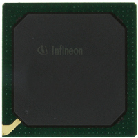
PEB20256E-V21 Infineon Technologies, PEB20256E-V21 Datasheet - Page 62

PEB20256E-V21
Manufacturer Part Number
PEB20256E-V21
Description
IC CONTROLLER INTERFACE 388-BGA
Manufacturer
Infineon Technologies
Datasheet
1.PEB20256E-V21.pdf
(232 pages)
Specifications of PEB20256E-V21
Function
Multichannel Network Interface Controller (MUNICH)
Interface
HDLC, PPP, Serial, TMA
Voltage - Supply
3 V ~ 3.6 V
Current - Supply
200mA
Power (watts)
3W
Operating Temperature
0°C ~ 70°C
Mounting Type
Surface Mount
Package / Case
388-BBGA
Lead Free Status / RoHS Status
Contains lead / RoHS non-compliant
Number Of Circuits
-
Other names
PEB20256E-V21
PEB20256E-V21IN
PEB20256E-V21IN
Available stocks
Company
Part Number
Manufacturer
Quantity
Price
Company:
Part Number:
PEB20256E-V21
Manufacturer:
MAX
Quantity:
63
Company:
Part Number:
PEB20256E-V21
Manufacturer:
Infineon Technologies
Quantity:
10 000
- Current page: 62 of 232
- Download datasheet (3Mb)
RHI
OFFSET
DescriptorID
NO
Data Sheet
Receive Host Initiated Interrupt
This bit indicates that the MUNICH256 shall generate a ’Receive Host
Initiated’ interrupt vector after it has finished processing the descriptor.
0
1
Offset of unused data section.
This bit field allows to reserve memory space in increments of DWORDs
for an additional header. If the marked descriptor is the first one of a new
packet the data management unit will write data at the address
ReceiveDataPointer+4xOFFSET.
Note: Offset x 4 must be smaller than NO.
Note: This option is not available in transparent mode.
This bit field is read by the data management unit and written back in the
corresponding interrupt status of a channel interrupt vector which is
generated by the data management unit. This value provides a link
between the descriptor and the corresponding interrupt vector.
Byte Number
This bit field defines the size of the receive data section allocated by the
host. The maximum buffer length is 65535 bytes and it has to be a
multiple of 4 bytes. Data bytes are stored in the receive data section
according to the selected mode (little endian or big endian).
Note: Please note that the device handles the status (CRC, flag and
Data management unit does not generate an interrupt vector
after it has processed the receive descriptor.
Data management unit generates an interrupt vector, as soon as
all data bytes are transferred into the current data section and the
status information is updated.
frame status) of frame based protocols (HDLC, PPP) internally in
the same way as payload data. Therefore byte number should
include four bytes more than the maximum length of incoming
frames. Nevertheless, the frame status will be deleted from the
end of the data stream and be attached as a status word to the
receive descriptor. The frame status will not be written to the data
section.
62
Functional Description
PEB 20256 E
PEF 20256 E
04.2001
Related parts for PEB20256E-V21
Image
Part Number
Description
Manufacturer
Datasheet
Request
R

Part Number:
Description:
Manufacturer:
Infineon Technologies AG
Datasheet:

Part Number:
Description:
Manufacturer:
Infineon Technologies AG
Datasheet:

Part Number:
Description:
Manufacturer:
Infineon Technologies AG
Datasheet:

Part Number:
Description:
Manufacturer:
Infineon Technologies AG
Datasheet:

Part Number:
Description:
Manufacturer:
Infineon Technologies AG
Datasheet:

Part Number:
Description:
Manufacturer:
Infineon Technologies AG
Datasheet:

Part Number:
Description:
Manufacturer:
Infineon Technologies AG
Datasheet:

Part Number:
Description:
16-bit microcontroller with 2x2 KByte RAM
Manufacturer:
Infineon Technologies AG
Datasheet:

Part Number:
Description:
NPN silicon RF transistor
Manufacturer:
Infineon Technologies AG
Datasheet:

Part Number:
Description:
NPN silicon RF transistor
Manufacturer:
Infineon Technologies AG
Datasheet:

Part Number:
Description:
NPN silicon RF transistor
Manufacturer:
Infineon Technologies AG
Datasheet:

Part Number:
Description:
NPN silicon RF transistor
Manufacturer:
Infineon Technologies AG
Datasheet:

Part Number:
Description:
Si-MMIC-amplifier in SIEGET 25-technologie
Manufacturer:
Infineon Technologies AG
Datasheet:

Part Number:
Description:
IGBT Power Module
Manufacturer:
Infineon Technologies AG
Datasheet:

Part Number:
Description:
IC for switching-mode power supplies
Manufacturer:
Infineon Technologies AG
Datasheet:


