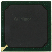
PEB20256E-V21 Infineon Technologies, PEB20256E-V21 Datasheet - Page 57

PEB20256E-V21
Manufacturer Part Number
PEB20256E-V21
Description
IC CONTROLLER INTERFACE 388-BGA
Manufacturer
Infineon Technologies
Datasheet
1.PEB20256E-V21.pdf
(232 pages)
Specifications of PEB20256E-V21
Function
Multichannel Network Interface Controller (MUNICH)
Interface
HDLC, PPP, Serial, TMA
Voltage - Supply
3 V ~ 3.6 V
Current - Supply
200mA
Power (watts)
3W
Operating Temperature
0°C ~ 70°C
Mounting Type
Surface Mount
Package / Case
388-BBGA
Lead Free Status / RoHS Status
Contains lead / RoHS non-compliant
Number Of Circuits
-
Other names
PEB20256E-V21
PEB20256E-V21IN
PEB20256E-V21IN
Available stocks
Company
Part Number
Manufacturer
Quantity
Price
Company:
Part Number:
PEB20256E-V21
Manufacturer:
MAX
Quantity:
63
Company:
Part Number:
PEB20256E-V21
Manufacturer:
Infineon Technologies
Quantity:
10 000
- Current page: 57 of 232
- Download datasheet (3Mb)
4.2
4.2.1
The time slot handler assigns any combination of time slots of ports configured in T1 or
E1, 4.096 MHz or 8.192 MHz mode to logical channels. The assigned time slots are
connected internally and the bit stream of one logical channel is mapped continuously
over the selected time slots. Since the receiver and the transmitter operate
independently of each other, the assignment of time slots to logical channels can be
done separately in receive and transmit direction. Any time slot can be assigned to any
channel and any sequence of time slots can be assigned to one channel.
In normal operation each time slot consists of eight bits and all bits are used for data
transmission. An available mask function provides the capability to mask selected bits,
which in turn are disabled for data transmission. This provides the possibility to operate
time slots with less than 64 kBit/s throughput. So, instead of mapping the bit stream of
one logical channel over all bits of the assigned time slots, the bit stream is mapped
continuously over all unmasked bits of the time slots belonging to that channel.
Masked bits are tri-stated in transmit direction. In receive direction masked data bits are
discarded.
Figure4-6
mode and time slots two and three are assigned to logical channel 5. The bit mask of
time slot two is set to FE
the third time slot is set to FD
Data Sheet
shows a simple assignment process. In this case one port is configured in E1
Time slot Handler
Channelized Modes
H
, which disables bit zero of that time slot, and the bit mask of
H
, which disables bit one.
57
Functional Description
PEB 20256 E
PEF 20256 E
04.2001
Related parts for PEB20256E-V21
Image
Part Number
Description
Manufacturer
Datasheet
Request
R

Part Number:
Description:
Manufacturer:
Infineon Technologies AG
Datasheet:

Part Number:
Description:
Manufacturer:
Infineon Technologies AG
Datasheet:

Part Number:
Description:
Manufacturer:
Infineon Technologies AG
Datasheet:

Part Number:
Description:
Manufacturer:
Infineon Technologies AG
Datasheet:

Part Number:
Description:
Manufacturer:
Infineon Technologies AG
Datasheet:

Part Number:
Description:
Manufacturer:
Infineon Technologies AG
Datasheet:

Part Number:
Description:
Manufacturer:
Infineon Technologies AG
Datasheet:

Part Number:
Description:
16-bit microcontroller with 2x2 KByte RAM
Manufacturer:
Infineon Technologies AG
Datasheet:

Part Number:
Description:
NPN silicon RF transistor
Manufacturer:
Infineon Technologies AG
Datasheet:

Part Number:
Description:
NPN silicon RF transistor
Manufacturer:
Infineon Technologies AG
Datasheet:

Part Number:
Description:
NPN silicon RF transistor
Manufacturer:
Infineon Technologies AG
Datasheet:

Part Number:
Description:
NPN silicon RF transistor
Manufacturer:
Infineon Technologies AG
Datasheet:

Part Number:
Description:
Si-MMIC-amplifier in SIEGET 25-technologie
Manufacturer:
Infineon Technologies AG
Datasheet:

Part Number:
Description:
IGBT Power Module
Manufacturer:
Infineon Technologies AG
Datasheet:

Part Number:
Description:
IC for switching-mode power supplies
Manufacturer:
Infineon Technologies AG
Datasheet:


