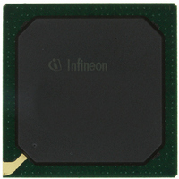
PEB20256E-V21 Infineon Technologies, PEB20256E-V21 Datasheet - Page 27

PEB20256E-V21
Manufacturer Part Number
PEB20256E-V21
Description
IC CONTROLLER INTERFACE 388-BGA
Manufacturer
Infineon Technologies
Datasheet
1.PEB20256E-V21.pdf
(232 pages)
Specifications of PEB20256E-V21
Function
Multichannel Network Interface Controller (MUNICH)
Interface
HDLC, PPP, Serial, TMA
Voltage - Supply
3 V ~ 3.6 V
Current - Supply
200mA
Power (watts)
3W
Operating Temperature
0°C ~ 70°C
Mounting Type
Surface Mount
Package / Case
388-BBGA
Lead Free Status / RoHS Status
Contains lead / RoHS non-compliant
Number Of Circuits
-
Other names
PEB20256E-V21
PEB20256E-V21IN
PEB20256E-V21IN
Available stocks
Company
Part Number
Manufacturer
Quantity
Price
Company:
Part Number:
PEB20256E-V21
Manufacturer:
MAX
Quantity:
63
Company:
Part Number:
PEB20256E-V21
Manufacturer:
Infineon Technologies
Quantity:
10 000
- Current page: 27 of 232
- Download datasheet (3Mb)
2.3
Signal Type Definitions:
The following signal type definitions are partly taken from the PCI Specification Rev. 2. 1:
I
O
t/s, I/O
s/t/s
o/d
Signal Name Conventions:
NCn
Reserved
Note: The signal type definition specifies the functional usage of a pin. This does not
Data Sheet
reflect necessarily the implementation of a pin, e.g. a pin defined of signal type
‘Input’ may be implemented with a bidirectional pad.
Pin Definition and functions
Input is a standard input- only signal.
Totem Pole Output is a standard active driver.
Tri-State or I/O is a bidirectional, tri-state input/output pin.
Sustained Tri-State is an active low tri-state signal owned and driven by
one and only agent at a time. The agent that drives an s/t/s pin low must
drive it high for at least one clock before letting it float. A new agent
cannot start driving a s/t/s signal any sooner than one clock after the
previous owner tri-states it. A pullup is required to sustain the inactive
state until another agent drives it, and must be provided by the central
resource.
Open Drain allows multiple devices to share a line as a wire-OR. A pull-
up is required to sustain the inactive state until another agent drives it,
and must be provided by the central resource.
No-connect Pin n
Such pins are not bonded with the silicon. Although any potential at
these pins will not impact the device it is recommended to leave them
unconnected. No-connect pins might be used for additional functionality
in later versions of the device. Leaving them unconnected will guarantee
hardware compatibility to later device versions.
Reserved pins are for vendor specific use only and should be connected
as recommended to guarantee normal operation.
27
Pin Description
PEB 20256 E
PEF 20256 E
04.2001
Related parts for PEB20256E-V21
Image
Part Number
Description
Manufacturer
Datasheet
Request
R

Part Number:
Description:
Manufacturer:
Infineon Technologies AG
Datasheet:

Part Number:
Description:
Manufacturer:
Infineon Technologies AG
Datasheet:

Part Number:
Description:
Manufacturer:
Infineon Technologies AG
Datasheet:

Part Number:
Description:
Manufacturer:
Infineon Technologies AG
Datasheet:

Part Number:
Description:
Manufacturer:
Infineon Technologies AG
Datasheet:

Part Number:
Description:
Manufacturer:
Infineon Technologies AG
Datasheet:

Part Number:
Description:
Manufacturer:
Infineon Technologies AG
Datasheet:

Part Number:
Description:
16-bit microcontroller with 2x2 KByte RAM
Manufacturer:
Infineon Technologies AG
Datasheet:

Part Number:
Description:
NPN silicon RF transistor
Manufacturer:
Infineon Technologies AG
Datasheet:

Part Number:
Description:
NPN silicon RF transistor
Manufacturer:
Infineon Technologies AG
Datasheet:

Part Number:
Description:
NPN silicon RF transistor
Manufacturer:
Infineon Technologies AG
Datasheet:

Part Number:
Description:
NPN silicon RF transistor
Manufacturer:
Infineon Technologies AG
Datasheet:

Part Number:
Description:
Si-MMIC-amplifier in SIEGET 25-technologie
Manufacturer:
Infineon Technologies AG
Datasheet:

Part Number:
Description:
IGBT Power Module
Manufacturer:
Infineon Technologies AG
Datasheet:

Part Number:
Description:
IC for switching-mode power supplies
Manufacturer:
Infineon Technologies AG
Datasheet:


