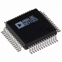
ADUC836BSZ Analog Devices Inc, ADUC836BSZ Datasheet - Page 40

ADUC836BSZ
Manufacturer Part Number
ADUC836BSZ
Description
16bit Dual ADC With Embedded 8 Bit MCU
Manufacturer
Analog Devices Inc
Series
MicroConverter® ADuC8xxr
Datasheet
1.ADUC836BSZ.pdf
(80 pages)
Specifications of ADUC836BSZ
Core Processor
8052
Core Size
8-Bit
Speed
12.58MHz
Connectivity
EBI/EMI, I²C, SPI, UART/USART
Peripherals
POR, PSM, PWM, Temp Sensor, WDT
Number Of I /o
34
Program Memory Size
62KB (62K x 8)
Program Memory Type
FLASH
Eeprom Size
4K x 8
Ram Size
2.25K x 8
Voltage - Supply (vcc/vdd)
2.7 V ~ 5.25 V
Data Converters
A/D 7x16b; D/A 1x12b
Oscillator Type
Internal
Operating Temperature
-40°C ~ 125°C
Package / Case
52-MQFP, 52-PQFP
Cpu Family
ADuC8xx
Device Core
8052
Device Core Size
8b
Frequency (max)
12.58MHz
Interface Type
I2C/SPI/UART
Total Internal Ram Size
2.25KB
# I/os (max)
26
Number Of Timers - General Purpose
3
Operating Supply Voltage (typ)
3.3/5V
Operating Supply Voltage (max)
5.25V
Operating Supply Voltage (min)
2.7V
On-chip Adc
2(2-chx16-bit)
On-chip Dac
1-chx12-bit
Instruction Set Architecture
CISC
Operating Temp Range
-40C to 125C
Operating Temperature Classification
Automotive
Mounting
Surface Mount
Pin Count
52
Package Type
MQFP
Package
52MQFP
Family Name
ADuC8xx
Maximum Speed
12.58 MHz
Operating Supply Voltage
3.3|5 V
Data Bus Width
8 Bit
Number Of Programmable I/os
26
Number Of Timers
3
Lead Free Status / RoHS Status
Lead free / RoHS Compliant
Lead Free Status / RoHS Status
Lead free / RoHS Compliant
Available stocks
Company
Part Number
Manufacturer
Quantity
Price
Company:
Part Number:
ADUC836BSZ
Manufacturer:
ADI
Quantity:
150
Company:
Part Number:
ADUC836BSZ
Manufacturer:
Analog Devices Inc
Quantity:
10 000
Part Number:
ADUC836BSZ
Manufacturer:
ADI/亚德诺
Quantity:
20 000
TIME INTERVAL COUNTER (WAKE-UP/RTC TIMER)
A time interval counter (TIC) is provided on-chip for:
The TIC is capable of timeout intervals ranging from 1/128th
second to 255 hours. Furthermore, this counter is clocked by the
crystal oscillator rather than the by PLL, and thus has the ability to
remain active in Power-Down mode and time long power-down
intervals.This has obvious applications for remote battery-powered
sensors where regular widely, spaced readings are required.
The TIC counter can easily be used to generate a real-time
clock. The hardware will count in seconds, minutes, and hours;
however, user software will have to count in days, months, and
years. The current time can be written to the timebase SFRs
(HTHSEC, SEC, MIN, and HOUR) while TCEN is low. When
the RTC timer is enabled (TCEN is set), the TCEN bit itself and
the HTHSEC, SEC, MIN, and HOUR Registers are not reset to
00H after a hardware or watchdog timer reset. This is to prevent
the need to recalibrate the real-time clock after a reset. However,
these registers will be reset to 00H after a power cycle (indepen-
dent of TCEN) or after any reset if TCEN is clear.
Six SFRs are associated with the time interval counter,TIMECON
being its control register. Depending on the configuration of the
IT0 and IT1 bits in TIMECON, the selected time counter register
overflow will clock the interval counter.When this counter is equal
to the time interval value loaded in the INTVAL SFR, the TII
bit (TIMECON.2) is set and generates an interrupt if enabled.
(See IEIP2 SFR description under the Interrupt System section.)
Bit
7
6
5
4
3
2
1
0
ADuC836
Periodically waking up the part from power-down
Implementing a real-time clock
Counting longer intervals than the standard 8051 compatible
timers are capable of
Name
–––
–––
ITS1
ITS0
STI
TII
TIEN
TCEN
Description
Reserved for Future Use
Reserved for Future Use. For future product code compatibility, this bit should be written as a 1.
Interval Timebase Selection Bits.
Written by user to determine the interval counter update rate.
ITS1
0
0
1
1
Single Time Interval Bit.
Set by user to generate a single interval timeout. If set, a timeout will clear the TIEN bit.
Cleared by user to allow the interval counter to be automatically reloaded and start counting again at each interval
timeout.
TIC Interrupt Bit.
Set when the 8-bit interval counter matches the value in the INTVAL SFR.
Cleared by user software.
Time Interval Enable Bit.
Set by user to enable the 8-bit time interval counter.
Cleared by user to disable and clear the contents of the 8-bit interval counter. To ensure that the 8-bit interval
counter is cleared, TIEN must be held low for at least 30.5 s (32 kHz).
Time Clock Enable Bit.
Set by user to enable the time clock to the time interval counters.
Cleared by user to disable the 32 kHz clock to the TIC and clear the 8-bit prescaler and the HTHSEC, SEC,
MIN, and HOURS SFRs. To ensure that these registers are cleared, TCEN must be held low for at least 30.5 s
(32 kHz). The time registers (HTHSEC, SEC, MIN, and HOUR) can be written only while TCEN is low.
ITS0
0
1
0
1
Table XVIII. TIMECON SFR Bit Designations
Interval Timebase
1/128 Second
Seconds
Minutes
Hours
–40–
If the ADuC836 is in Power-Down mode, again with TIC inter-
rupt enabled, the TII bit will wake up the device and resume
code execution by vectoring directly to the TIC interrupt service
vector address at 0053H. The TIC-related SFRs are described in
Table XVIII with a block diagram of the TIC shown in Figure 33.
TIME INTERVAL COUNTER INTERRUPT
TCEN
INTERVAL TIMEOUT
32.768kHz EXTERNAL CRYSTAL
Figure 33.TIC, Simplified Block Diagram
HUNDREDTHS COUNTER
SECOND COUNTER
MINUTE COUNTER
HOUR COUNTER
PRESCALER
HOUR
8-BIT
HTHSEC
SEC
MIN
INTERVAL COUNTER
INTVAL SFR
EQUAL?
8-BIT
SELECTION
TIMEBASE
INTERVAL
ITS0, 1
MUX
REV. A
TIEN


