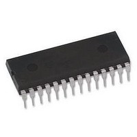
ATMEGA168PA-PU Atmel, ATMEGA168PA-PU Datasheet - Page 243

ATMEGA168PA-PU
Manufacturer Part Number
ATMEGA168PA-PU
Description
MCU, 8BIT, AVR, 16K FLASH, 28PDIP
Manufacturer
Atmel
Datasheet
1.ATMEGA48A-PU.pdf
(566 pages)
Specifications of ATMEGA168PA-PU
Controller Family/series
Atmega
No. Of I/o's
23
Eeprom Memory Size
512Byte
Ram Memory Size
1KB
Cpu Speed
20MHz
No.
RoHS Compliant
Core Size
8bit
Program Memory Size
16KB
Oscillator Type
External, Internal
Rohs Compliant
Yes
Available stocks
Company
Part Number
Manufacturer
Quantity
Price
Company:
Part Number:
ATMEGA168PA-PU
Manufacturer:
TI
Quantity:
1 240
- Current page: 243 of 566
- Download datasheet (23Mb)
ATmega48A/48PA/88A/88PA/168A/168PA/328/328
• Bit 7 – TWINT: TWI Interrupt Flag
This bit is set by hardware when the TWI has finished its current job and expects application
software response. If the I-bit in SREG and TWIE in TWCR are set, the MCU will jump to the
TWI Interrupt Vector. While the TWINT Flag is set, the SCL low period is stretched. The TWINT
Flag must be cleared by software by writing a logic one to it. Note that this flag is not automati-
cally cleared by hardware when executing the interrupt routine. Also note that clearing this flag
starts the operation of the TWI, so all accesses to the TWI Address Register (TWAR), TWI Sta-
tus Register (TWSR), and TWI Data Register (TWDR) must be complete before clearing this
flag.
• Bit 6 – TWEA: TWI Enable Acknowledge Bit
The TWEA bit controls the generation of the acknowledge pulse. If the TWEA bit is written to
one, the ACK pulse is generated on the TWI bus if the following conditions are met:
1. The device’s own slave address has been received.
2. A general call has been received, while the TWGCE bit in the TWAR is set.
3. A data byte has been received in Master Receiver or Slave Receiver mode.
By writing the TWEA bit to zero, the device can be virtually disconnected from the 2-wire Serial
Bus temporarily. Address recognition can then be resumed by writing the TWEA bit to one
again.
• Bit 5 – TWSTA: TWI START Condition Bit
The application writes the TWSTA bit to one when it desires to become a Master on the 2-wire
Serial Bus. The TWI hardware checks if the bus is available, and generates a START condition
on the bus if it is free. However, if the bus is not free, the TWI waits until a STOP condition is
detected, and then generates a new START condition to claim the bus Master status. TWSTA
must be cleared by software when the START condition has been transmitted.
• Bit 4 – TWSTO: TWI STOP Condition Bit
Writing the TWSTO bit to one in Master mode will generate a STOP condition on the 2-wire
Serial Bus. When the STOP condition is executed on the bus, the TWSTO bit is cleared auto-
matically. In Slave mode, setting the TWSTO bit can be used to recover from an error condition.
This will not generate a STOP condition, but the TWI returns to a well-defined unaddressed
Slave mode and releases the SCL and SDA lines to a high impedance state.
• Bit 3 – TWWC: TWI Write Collision Flag
The TWWC bit is set when attempting to write to the TWI Data Register – TWDR when TWINT is
low. This flag is cleared by writing the TWDR Register when TWINT is high.
• Bit 2 – TWEN: TWI Enable Bit
The TWEN bit enables TWI operation and activates the TWI interface. When TWEN is written to
one, the TWI takes control over the I/O pins connected to the SCL and SDA pins, enabling the
slew-rate limiters and spike filters. If this bit is written to zero, the TWI is switched off and all TWI
transmissions are terminated, regardless of any ongoing operation.
• Bit 1 – Reserved
This bit is a reserved bit and will always read as zero.
243
8271C–AVR–08/10
Related parts for ATMEGA168PA-PU
Image
Part Number
Description
Manufacturer
Datasheet
Request
R

Part Number:
Description:
Manufacturer:
Atmel Corporation
Datasheet:

Part Number:
Description:
Manufacturer:
Atmel Corporation
Datasheet:

Part Number:
Description:
Manufacturer:
ATMEL Corporation
Datasheet:

Part Number:
Description:
IC AVR MCU 16K 20MHZ 32TQFP
Manufacturer:
Atmel
Datasheet:

Part Number:
Description:
IC AVR MCU 16K 20MHZ 32-QFN
Manufacturer:
Atmel
Datasheet:

Part Number:
Description:
IC AVR MCU 16K 20MHZ 28DIP
Manufacturer:
Atmel
Datasheet:

Part Number:
Description:
MCU AVR 16K FLASH 15MHZ 32-TQFP
Manufacturer:
Atmel
Datasheet:

Part Number:
Description:
MCU AVR 16K FLASH 15MHZ 32-QFN
Manufacturer:
Atmel
Datasheet:

Part Number:
Description:
IC AVR MCU 16K 20MHZ 32TQFP
Manufacturer:
Atmel
Datasheet:

Part Number:
Description:
MCU AVR 16KB FLASH 20MHZ 32QFN
Manufacturer:
Atmel
Datasheet:

Part Number:
Description:
MCU AVR 16KB FLASH 20MHZ 32TQFP
Manufacturer:
Atmel
Datasheet:

Part Number:
Description:
IC MCU AVR 16K FLASH 32-QFN
Manufacturer:
Atmel
Datasheet:


