TMOV25SP385M Littelfuse Inc, TMOV25SP385M Datasheet - Page 8
TMOV25SP385M
Manufacturer Part Number
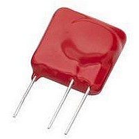
TMOV25SP385M
Description
TMOV VARISTOR PB FREE 25S
Manufacturer
Littelfuse Inc
Series
iTMOV®r
Specifications of TMOV25SP385M
Varistor Voltage
682V
Current-surge
20kA
Number Of Circuits
1
Maximum Ac Volts
385VAC
Energy
430J
Package / Case
Disc 25mm 3-Lead
Suppressor Type
Varistor
Peak Surge Current @ 8/20µs
20000A
Varistor Case
25mm DISC
Clamping Voltage Vc Max
1010V
Peak Energy (10/1000us)
430J
Voltage Rating Vdc
682V
Voltage Rating Vac
385V
Lead Free Status / RoHS Status
Lead free / RoHS Compliant
Maximum Dc Volts
-
Lead Free Status / Rohs Status
Lead free / RoHS Compliant


Product Selection Worksheet
Step 2. Calculate voltage value.
Step 1. Determine the circuit’s operating parameters.
(complete as much of the following information as possible).
1-a. Source and path of the transient
1-b. Normal operating voltage of protected device
1-c. Tolerance of normal operating voltage (1-b)
1-d. Max. allowable voltage of protected device
1-e. Maximum expected surge current and number of hits
(Specify 8x20μs waveform equivalent of surge current)
1-f. Maximum energy applied to device in surge event
1-g. Maximum power applied to device in surge event
1-h. Maximum allowable varistor capacitance (@1kHz; 0V
bias)
will not impair the functionality of the circuit)
1-i. Required safety standards
(Name of standards required, such as UL, CSA, VDE, etc.)
2-a. The required varistor voltage value should be equal to:
If the tolerance is not known, multiply the operating voltage of
protected equipment or device by 1.10 to 1.25 (i.e. 10–25% above
operating voltage value).
____ Operating voltage AC (V) x 1.414 = ______________________
(1.10 to 1.25) = _____________ Required varistor voltage (V)
the operating voltage of the protected equipment or device*
____Operating voltage of equipment or device (V
________Operating voltage of equipment or device (V
(This is the maximum capacitance of the varistor device that
If the operating voltage is in AC (V
________ Source
________ (V
________ (V)
________ (V
________ (A)
________ (Joules) (E=1.4xVxIxT)
________ (W) (P=VxI)
________ (pF)
_________Tolerance (V) = _____________________
the tolerance of the operating voltage.
AC
AC
) , or ________ (V)
) or ________ (V)
or ________ Unknown
________ Path
________ (# of hits)
- or -
x
+
+
Required varistor voltage (V)
Operating voltage (V)
RMS
RMS
RMS
) convert to V
DC
DC
DC
DC
DC
.
)
Revision: November 5, 2009
RMS
Varistor Products
)
DC
DC
4
Step 3. Guidelines for Selecting a Varistor
If a response to one of the requirements below is "False," refer
to appropriate corrective action notes (A-F) at bottom of list:
3-a. Varistor voltage value - Tolerance of varistor ≥ Required
varistor voltage value (2-a)
3-b. Varistor maximum clamping voltage value Maximum
allowable voltage of protected equipment or device (1-d)
(Max. current should be less than or equal to the current at which
maximum clamping voltage is measured).
3-c. Varistor maximum peak current value Maximum expected
surge current (1-e)
Note: If surge current waveform is not 8 x 20μs, use Pulse
Lifetime Ratings curves.
3-d. Varistor maximum energy rating Maximum energy
applied to system (1-f)
3-e. Varistor maximum rated power Maximum power applied
to system (1-g)
3-f. Varistor capacitance Maximum allowable system
capacitance (1-h)
Corrective action notes:
A. Select next varistor on the list (i.e. next varistor with
increasing varistor voltage value) and then re-verify 3-a.
B. Select previous varistor on the list (i.e. previous varistor with
decreasing varistor voltage value) and then re-verify 3-b.
C. Select next varistor diameter level and then re-verify 3-c.*
D. Select next varistor diameter level and then re-verify 3-d.*
E. Select next varistor diameter level and then re-verify 3-e.*
F . Select lower varistor diameter level and then re-verify 3-c,
3-d, 3-e and 3-f.*
* If varistor voltage is below 82V, selecting an 82V ROV may
be preferable over a higher diameter part.
Step 4. Verify the following system conditions.
4-a. Leakage current of the selected varistor is appropriate for
the circuit ______True ______False
4-b. Verify the performance of the varistor under fault
conditions ______Verified
Users should Independently evaluate the suitability of, and test
each MOV device in their application for safety and suitability
with the end application.
Please refer to www.littelfuse.com for current information.
Specifications are subject to change without notice.
______True ______False (A)
______True______False (B)
______True ______False (C)
______True ______False (D)
______True ______False (E)
______True ______False (F)
©2009 Littelfuse, Inc.
Related parts for TMOV25SP385M
Image
Part Number
Description
Manufacturer
Datasheet
Request
R

Part Number:
Description:
FUSEHOLDER 20A MINI INLINE CRIMP
Manufacturer:
Littelfuse Inc
Datasheet:

Part Number:
Description:
FUSEHOLDER BODY ATO INLINE PNLMT
Manufacturer:
Littelfuse Inc
Datasheet:

Part Number:
Description:
FUSE 2A 63V FAST 1206
Manufacturer:
Littelfuse Inc
Datasheet:
Part Number:
Description:
FUSE 1.25A 63V FAST 1206
Manufacturer:
Littelfuse Inc
Datasheet:
Part Number:
Description:
FUSE .250A 125V FAST 1206
Manufacturer:
Littelfuse Inc
Datasheet:
Part Number:
Description:
FUSE 4A 32V FAST 1206
Manufacturer:
Littelfuse Inc
Datasheet:
Part Number:
Description:
FUSE 1.75A 63V FAST 1206
Manufacturer:
Littelfuse Inc
Datasheet:

Part Number:
Description:
FUSE 1A 32V FST 0603 LEADFREE TR
Manufacturer:
Littelfuse Inc
Datasheet:

Part Number:
Description:
FUSE 1A 32V FAST SLIM 0402
Manufacturer:
Littelfuse Inc
Datasheet:

Part Number:
Description:
FUSE 2A 125V FAST NANO2 SMD
Manufacturer:
Littelfuse Inc
Datasheet:

Part Number:
Description:
FUSE .250A 125V FAST NANO2 SMD
Manufacturer:
Littelfuse Inc
Datasheet:

Part Number:
Description:
FUSE .500A 125V FAST NANO2 SMD
Manufacturer:
Littelfuse Inc
Datasheet:

Part Number:
Description:
FUSE 1.5A 125V FAST NANO2 SMD
Manufacturer:
Littelfuse Inc
Datasheet:

Part Number:
Description:
FUSE 4A 125V FAST NANO2 SMD
Manufacturer:
Littelfuse Inc
Datasheet:

Part Number:
Description:
FUSE 1A 125V FAST NANO2 SMD
Manufacturer:
Littelfuse Inc
Datasheet: