TMOV25SP385M Littelfuse Inc, TMOV25SP385M Datasheet - Page 16
TMOV25SP385M
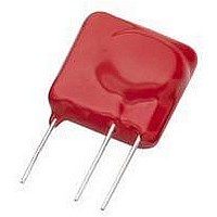
Manufacturer Part Number
TMOV25SP385M
Description
TMOV VARISTOR PB FREE 25S
Manufacturer
Littelfuse Inc
Series
iTMOV®r
Specifications of TMOV25SP385M
Varistor Voltage
682V
Current-surge
20kA
Number Of Circuits
1
Maximum Ac Volts
385VAC
Energy
430J
Package / Case
Disc 25mm 3-Lead
Suppressor Type
Varistor
Peak Surge Current @ 8/20µs
20000A
Varistor Case
25mm DISC
Clamping Voltage Vc Max
1010V
Peak Energy (10/1000us)
430J
Voltage Rating Vdc
682V
Voltage Rating Vac
385V
Lead Free Status / RoHS Status
Lead free / RoHS Compliant
Maximum Dc Volts
-
Lead Free Status / Rohs Status
Lead free / RoHS Compliant


------------ -
c
the field lowered barrier, and is thermally activated, at least
above about 25ºC. For semiconductor abrupt P-N junction
diodes. The relationship is:
Where:
(V
(V) = applied voltage,
(q) = electron charge,
(es) = semiconductor permittivity and
(N) = carrier concentration.
From this relationship the ZnO carrier concentration, N,
was determined to be about 2 x 10
In addition, the width of the depletion layer was calculated
to be about 1000 Angstrom units. Single junction studies
also support the diode model.
Figure 5, shows an energy band diagram for a ZnO-grain
boundary-ZnO junction . The left-hand grain is forward
biased, V
depletion layer widths are X
barrier heights are f
is f
f
increase in conduction.
The barrier height f
measured as a function of applied voltage, and is
presented in Figure 6. The rapid decrease in the barrier at
high voltage represents the onset of nonlinear conduction.
2
R
1
FIGURE 4. CAPACITANCE-VOLTAGE BEHAVIOR OF
n
b
is increased, leading to a lowering of the barrier and an
2
O
) = barrier voltage,
/cm
. As the voltage bias is increased, f
(10
4
14
L
, and the right side is reverse biased to V
4
3
2
)
VARISTOR RESEMBLES A SEMICONDUCTOR
ABRUPT-JUNCTION REVERSED BIASED DIODE
Nd ~ 2 x 10
0
L
------ -
C
L
1
of a low voltage varistor was
2
and f
17
=
0.4
/cm
2 V
------------------------- -
(
V A PER BOUNDARY
R
q sN
3
. The zero biased barrier height
b
L
+
and X
V
)
0.8
17
R
, and the respective
per cm
L
is decreased and
3
.
1.2
R
. The
Revision: November 5, 2009
Varistor Products
12
Transport mechanisms in the nonlinear region are very
complicated and are still the subject of active research.
Most theories draw their inspiration from semiconductor
transport theory and is not covered in detail in this docu-
ment.
FIGURE 5. ENERGY BAND DIAGRAM OF A
FIGURE 6. THERMAL BARRIER vs APPLIED VOLTAGE
1.0
0.8
0.6
0.4
0.2
0
0
E
E
E
E
C
V
f
I
ZnO-GRAINBOUNDARY-ZnO JUNCTION
V
L
4
L
X
Please refer to www.littelfuse.com for current information.
L
VOLTAGE (V)
Specifications are subject to change without notice.
0 B
8
0
X
R
R
F
12
V
R
©2009 Littelfuse, Inc.
16
Related parts for TMOV25SP385M
Image
Part Number
Description
Manufacturer
Datasheet
Request
R

Part Number:
Description:
FUSEHOLDER 20A MINI INLINE CRIMP
Manufacturer:
Littelfuse Inc
Datasheet:

Part Number:
Description:
FUSEHOLDER BODY ATO INLINE PNLMT
Manufacturer:
Littelfuse Inc
Datasheet:

Part Number:
Description:
FUSE 2A 63V FAST 1206
Manufacturer:
Littelfuse Inc
Datasheet:
Part Number:
Description:
FUSE 1.25A 63V FAST 1206
Manufacturer:
Littelfuse Inc
Datasheet:
Part Number:
Description:
FUSE .250A 125V FAST 1206
Manufacturer:
Littelfuse Inc
Datasheet:
Part Number:
Description:
FUSE 4A 32V FAST 1206
Manufacturer:
Littelfuse Inc
Datasheet:
Part Number:
Description:
FUSE 1.75A 63V FAST 1206
Manufacturer:
Littelfuse Inc
Datasheet:

Part Number:
Description:
FUSE 1A 32V FST 0603 LEADFREE TR
Manufacturer:
Littelfuse Inc
Datasheet:

Part Number:
Description:
FUSE 1A 32V FAST SLIM 0402
Manufacturer:
Littelfuse Inc
Datasheet:

Part Number:
Description:
FUSE 2A 125V FAST NANO2 SMD
Manufacturer:
Littelfuse Inc
Datasheet:

Part Number:
Description:
FUSE .250A 125V FAST NANO2 SMD
Manufacturer:
Littelfuse Inc
Datasheet:

Part Number:
Description:
FUSE .500A 125V FAST NANO2 SMD
Manufacturer:
Littelfuse Inc
Datasheet:

Part Number:
Description:
FUSE 1.5A 125V FAST NANO2 SMD
Manufacturer:
Littelfuse Inc
Datasheet:

Part Number:
Description:
FUSE 4A 125V FAST NANO2 SMD
Manufacturer:
Littelfuse Inc
Datasheet:

Part Number:
Description:
FUSE 1A 125V FAST NANO2 SMD
Manufacturer:
Littelfuse Inc
Datasheet: