TMOV25SP385M Littelfuse Inc, TMOV25SP385M Datasheet - Page 57
TMOV25SP385M
Manufacturer Part Number
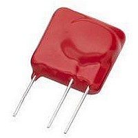
TMOV25SP385M
Description
TMOV VARISTOR PB FREE 25S
Manufacturer
Littelfuse Inc
Series
iTMOV®r
Specifications of TMOV25SP385M
Varistor Voltage
682V
Current-surge
20kA
Number Of Circuits
1
Maximum Ac Volts
385VAC
Energy
430J
Package / Case
Disc 25mm 3-Lead
Suppressor Type
Varistor
Peak Surge Current @ 8/20µs
20000A
Varistor Case
25mm DISC
Clamping Voltage Vc Max
1010V
Peak Energy (10/1000us)
430J
Voltage Rating Vdc
682V
Voltage Rating Vac
385V
Lead Free Status / RoHS Status
Lead free / RoHS Compliant
Maximum Dc Volts
-
Lead Free Status / Rohs Status
Lead free / RoHS Compliant


©2009 Littelfuse, Inc.
Specifications are subject to change without notice.
Please refer to www.littelfuse.com/series/AUML.html for current information.
A Load Dump transient occurs when the alternator load in
the automobile is abruptly reduced. The worst case scenario
of this transient occurs when the battery is disconnected
while operating at full rated load. There are a number of
different Load Dump specifications in existence in the
automotive industry, with the most common one being that
recommended by the Society of Automotive Engineers,
specification #SAE J1113. Because of the diversity of these
Load Dump specifications Littelfuse defines the Load
Dump energy capability of the AUML suppressor range as
that energy dissipated by the device itself, independent
of the test circuit setup. The resultant Load Dump energy
handling capability serves as an excellent figure of merit for
the AUML suppressor. Standard Load Dump specifications
require a device capability of 10 pulses at rated energy,
across a temperature range of -40ºC to +125ºC. This
capability requirement is well within the ratings of all of the
AUML Series (Figure 6 on next page).
Further testing on the AUML Series has concentrated
on extending the number of Load Dump pulses, at rated
energy, which are applied to the devices. The reliability
information thus generated gives an indication of the
inherent capability of these devices. As an example of
device durability the 1210 size has been subjected to over
2000 pulses at its rated energy of 3 joules (J); the 1812 size
has been pulsed over 1000 times at 6J and 2220 size has
been pulsed at its rated energy of 25J over 300 times. In
all cases there has been little or no change in the device
characteristics (Figure 7 on next page).
Temperature Effects
In the leakage region of the AUML suppressor, the device
characteristics approaches a linear (ohmic) relationship
and shows a temperature dependent affect. In this region
the suppressor is in a high resistance mode (approaching
10
at maximum rated voltage are in the microamp range.
When clamping transients at higher currents (at and above
Load Dump Energy Capability
Speed of Response
The clamping action of the AUML suppressor depends
on a conduction mechanism similar to that of other
semiconductor devices (i.e. P-N Junctions). The apparent
slow response time often associated with transient
voltage suppressors (Zeners, MOVs) is often due to
parasitic inductance in the package and leads of the
device and less dependent of the basic material (Silicon,
Z
response time of any suppressor is its lead induc-tance.
The AUML suppressor is a surface mount device, with no
leads or external packaging, and thus, it has virtually zero
inductance. The actual response time of a AUML surge
suppressor is in the 1 to 5 ns range, more than sufficient
for the transients which are likely to be encountered in an
automotive environment.
N
O). Thus, the single most critical element affecting the
6
Ω) and appears as a near open-circuit. Leakage currents
Varistor Products
Surface Mount Multilayer Varistors (MLVs) > AUML Series
Revision: November 5, 2009
53
The very high energy absorption capability of the AUML
suppressor is achieved by means of a highly controlled
manufacturing process. This technology ensures that a
large volume of suppressor material, with an interdigitated
layer construction, is available for energy absorption in an
extremely small package. Unlike equivalent rated Silicon
TVS diodes, the entire AUML device volume is available to
dissipate the Load Dump energy.
Hence, the peak temperatures generated by the Load
Dump transient are significantly lower and evenly dissipated
throughout the complete device (Figure 5 below). This
even energy dissipation ensures that there are lower peak
temperatures generated at the P-N grain boundaries of the
AUML suppressor.
There are a number of different size devices available in the
AUML Series, each one with a load dump energy rating,
which is size dependent.
Experience has shown that while the effects of a load dump
tranient is of real concern, its frequency of occurrence is
much less than thoe of low energy inductive spikes. Such
low energy inductive spikes may be generated as a result
of motors switching on and off, from ESD occurrances, fuse
blowing, etc. It is essential that the suppression technology
selected also has the capability to suppress such transients.
Testing on the V18AUMLA2220 has shown that after being
subjected to a repetitive energy pulse of 2J, over 6000
times, no characteristic changes have occurred (Figure 8 on
next page).
the 10mA range), the AUML suppressor approaches
a 1-10 characteristic. In this region the characteristics
of the AUML are virtually temperature independent.
Figure 3 shows the typical effect of temperature on
the V-I characteristics of the AUML suppressor.
Figure 5
Multilayer Internal Construction
AUML Varistor Series
Related parts for TMOV25SP385M
Image
Part Number
Description
Manufacturer
Datasheet
Request
R

Part Number:
Description:
FUSEHOLDER 20A MINI INLINE CRIMP
Manufacturer:
Littelfuse Inc
Datasheet:

Part Number:
Description:
FUSEHOLDER BODY ATO INLINE PNLMT
Manufacturer:
Littelfuse Inc
Datasheet:

Part Number:
Description:
FUSE 2A 63V FAST 1206
Manufacturer:
Littelfuse Inc
Datasheet:
Part Number:
Description:
FUSE 1.25A 63V FAST 1206
Manufacturer:
Littelfuse Inc
Datasheet:
Part Number:
Description:
FUSE .250A 125V FAST 1206
Manufacturer:
Littelfuse Inc
Datasheet:
Part Number:
Description:
FUSE 4A 32V FAST 1206
Manufacturer:
Littelfuse Inc
Datasheet:
Part Number:
Description:
FUSE 1.75A 63V FAST 1206
Manufacturer:
Littelfuse Inc
Datasheet:

Part Number:
Description:
FUSE 1A 32V FST 0603 LEADFREE TR
Manufacturer:
Littelfuse Inc
Datasheet:

Part Number:
Description:
FUSE 1A 32V FAST SLIM 0402
Manufacturer:
Littelfuse Inc
Datasheet:

Part Number:
Description:
FUSE 2A 125V FAST NANO2 SMD
Manufacturer:
Littelfuse Inc
Datasheet:

Part Number:
Description:
FUSE .250A 125V FAST NANO2 SMD
Manufacturer:
Littelfuse Inc
Datasheet:

Part Number:
Description:
FUSE .500A 125V FAST NANO2 SMD
Manufacturer:
Littelfuse Inc
Datasheet:

Part Number:
Description:
FUSE 1.5A 125V FAST NANO2 SMD
Manufacturer:
Littelfuse Inc
Datasheet:

Part Number:
Description:
FUSE 4A 125V FAST NANO2 SMD
Manufacturer:
Littelfuse Inc
Datasheet:

Part Number:
Description:
FUSE 1A 125V FAST NANO2 SMD
Manufacturer:
Littelfuse Inc
Datasheet: