TMOV25SP385M Littelfuse Inc, TMOV25SP385M Datasheet - Page 19
TMOV25SP385M
Manufacturer Part Number
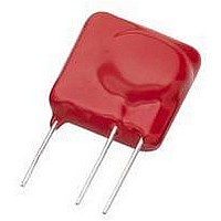
TMOV25SP385M
Description
TMOV VARISTOR PB FREE 25S
Manufacturer
Littelfuse Inc
Series
iTMOV®r
Specifications of TMOV25SP385M
Varistor Voltage
682V
Current-surge
20kA
Number Of Circuits
1
Maximum Ac Volts
385VAC
Energy
430J
Package / Case
Disc 25mm 3-Lead
Suppressor Type
Varistor
Peak Surge Current @ 8/20µs
20000A
Varistor Case
25mm DISC
Clamping Voltage Vc Max
1010V
Peak Energy (10/1000us)
430J
Voltage Rating Vdc
682V
Voltage Rating Vac
385V
Lead Free Status / RoHS Status
Lead free / RoHS Compliant
Maximum Dc Volts
-
Lead Free Status / Rohs Status
Lead free / RoHS Compliant


Specifications are subject to change without notice.
Please refer to www.littelfuse.com for current information.
©2009 Littelfuse, Inc.
FIGURE 13. TEMPERATURE DEPENDENCE OF THE CHARACTER-
Leakage Region of Operation
At low current levels, the V-I Curve approaches a linear
(ohmic) relationship and shows a significant temperature
dependence. The varistor is in a high resistance mode
(approaching 10
nonlinear resistance component (R
cause (R
insignificant compared to (R
For a given varistor device, capacitance remains approxi-
mately constant over a wide range of voltage and frequen-
cy in the leakage region. The value of capacitance drops
only slightly as voltage is applied to the varistor. As the
voltage approaches the nominal varistor voltage, the ca-
pacitance decreases. Capacitance remains nearly constant
with frequency change up to 100 kHz. Similarly, the change
with temperature is small, the 25ºC value of capacitance
being well with +/-10% from -40ºC to +125ºC.
The temperature effect of the V-I characteristic curve in the
leakage region is shown in Figure 13. A distinct tempera-
ture dependence is noted.
FIGURE 12. EQUIVALENT CIRCUIT AT LOW CURRENTS
100
80
60
50
40
30
20
10
10
-9
OFF
) in parallel will predominate. Also, (R
ISTIC CURVE IN THE LEAKAGE REGION
10
-8
25 50
9
Ω) and appears as an open circuit. The
C
10
VARISTOR CURRENT (A
75
-7
100
10
OFF
125
-6
L
).
SPECIMEN V130LA10A
o
C
10
R
X
OFF
-5
) can be ignored be-
DC
10
Varistor Products
)
-4
10
ON
-3
) will be
Revision: November 5, 2009
10
-2
15
NOTE: Typical Temperature Coefficient of Voltage vs Current, 14mm
Size, 55
The relation between the leakage current (I) and tempera-
ture (T) is
The temperature variation, in effect, corresponds to a
change in (R
tance value even at elevated temperatures. For example, it
is still in the range of 10MΩ to 100MΩ at 125ºC.
Although (R
The relationship is approximately linear with inverse fre-
quency.
If however, the parallel combination of (R
dominantly capacitive at any frequency of interest. This is
because the capacitive reactance also varies approximately
linearly with 1/f.
At higher currents, at and above the mA range, tempera-
ture variation becomes minimal. The plot of the tempera-
ture coefficient (dV/dT) is given in Figure 14. It should be
noted that the temperature coefficient is negative (-) and
decreases as current rises. In the clamping voltage range
of the varistor (I > 1A), the temperature dependency ap-
proaches zero.
FIGURE 14. RELATION OF TEMPERATURE COEFFICIENT
-0.1
-0.2
-0.3
-0.4
-0.5
0.1
0
10
I = I
where:
o
-5
SAMPLE TYPE
V130LA10A
C to 125
O
10
OFF
OFF
-4
DV/DT TO VARISTOR CURRENT
) is a high resistance it varies with frequency.
V22ZA3
o
). However, (R
C.
I
k
V
O
10
B
-3
= constant
= Boltzmann’s Constant
= 0.9eV
-V
LEAKAGE REGION
B
/kT
10
-2
CURRENT (A)
OFF
10
) remains at a high resis-
-1
10
0
OPERATION
NORMAL
OFF
10
) and (ºC) is pre-
1
10
2
10
3
Related parts for TMOV25SP385M
Image
Part Number
Description
Manufacturer
Datasheet
Request
R

Part Number:
Description:
FUSEHOLDER 20A MINI INLINE CRIMP
Manufacturer:
Littelfuse Inc
Datasheet:

Part Number:
Description:
FUSEHOLDER BODY ATO INLINE PNLMT
Manufacturer:
Littelfuse Inc
Datasheet:

Part Number:
Description:
FUSE 2A 63V FAST 1206
Manufacturer:
Littelfuse Inc
Datasheet:
Part Number:
Description:
FUSE 1.25A 63V FAST 1206
Manufacturer:
Littelfuse Inc
Datasheet:
Part Number:
Description:
FUSE .250A 125V FAST 1206
Manufacturer:
Littelfuse Inc
Datasheet:
Part Number:
Description:
FUSE 4A 32V FAST 1206
Manufacturer:
Littelfuse Inc
Datasheet:
Part Number:
Description:
FUSE 1.75A 63V FAST 1206
Manufacturer:
Littelfuse Inc
Datasheet:

Part Number:
Description:
FUSE 1A 32V FST 0603 LEADFREE TR
Manufacturer:
Littelfuse Inc
Datasheet:

Part Number:
Description:
FUSE 1A 32V FAST SLIM 0402
Manufacturer:
Littelfuse Inc
Datasheet:

Part Number:
Description:
FUSE 2A 125V FAST NANO2 SMD
Manufacturer:
Littelfuse Inc
Datasheet:

Part Number:
Description:
FUSE .250A 125V FAST NANO2 SMD
Manufacturer:
Littelfuse Inc
Datasheet:

Part Number:
Description:
FUSE .500A 125V FAST NANO2 SMD
Manufacturer:
Littelfuse Inc
Datasheet:

Part Number:
Description:
FUSE 1.5A 125V FAST NANO2 SMD
Manufacturer:
Littelfuse Inc
Datasheet:

Part Number:
Description:
FUSE 4A 125V FAST NANO2 SMD
Manufacturer:
Littelfuse Inc
Datasheet:

Part Number:
Description:
FUSE 1A 125V FAST NANO2 SMD
Manufacturer:
Littelfuse Inc
Datasheet: