TMOV25SP385M Littelfuse Inc, TMOV25SP385M Datasheet - Page 21
TMOV25SP385M
Manufacturer Part Number
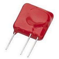
TMOV25SP385M
Description
TMOV VARISTOR PB FREE 25S
Manufacturer
Littelfuse Inc
Series
iTMOV®r
Specifications of TMOV25SP385M
Varistor Voltage
682V
Current-surge
20kA
Number Of Circuits
1
Maximum Ac Volts
385VAC
Energy
430J
Package / Case
Disc 25mm 3-Lead
Suppressor Type
Varistor
Peak Surge Current @ 8/20µs
20000A
Varistor Case
25mm DISC
Clamping Voltage Vc Max
1010V
Peak Energy (10/1000us)
430J
Voltage Rating Vdc
682V
Voltage Rating Vac
385V
Lead Free Status / RoHS Status
Lead free / RoHS Compliant
Maximum Dc Volts
-
Lead Free Status / Rohs Status
Lead free / RoHS Compliant


Specifications are subject to change without notice.
Please refer to www.littelfuse.com for current information.
©2009 Littelfuse, Inc.
Speed of Response and Rate Effects
The varistor action depends on a conduction mechanism
similar to that of other semiconductor devices. For this
reason, conduction occurs very rapidly, with no apparent
time lag – even into the nanosecond (ns) range. Figure 18,
shows a composite photograph of two voltage traces with
and without a varistor inserted in a very low inductance
impulse generator. The second trace (which is not synchro-
nized with the first, but merely superimposed on the oscil-
loscope screen) shows that the voltage clamping effect of
the varistor occurs in less than 1.0 ns.
In the conventional lead–mounted devices, the inductance
of the leads would completely mask the fast action of the
varistor; therefore, the test circuit for Figure 18, required
insertion of a small piece of varistor material in a coaxial
line to demonstrate the intrinsic varistor response.
Tests made on lead– mounted devices, even with careful
attention to minimizing lead length, show that the voltages
induced in the loop formed by the leads contribute a sub-
stantial part of the voltage appearing across the terminals
of a varistor at high current and fast current rise. Fortu-
nately, the currents which can be delivered by a transient
source are invariably slower in rise time than the observed
voltage transients. The applications most frequently
encountered for varistors involve current rise times longer
than 0.5μs.
Voltage rate-of-rise is not the best term to use when dis-
cussing the response of a varistor to a fast impulse (unlike
spark gaps where a finite time is involved in switching from
nonconducting to conducting state). The response time of
the varistor to the transient current that a circuit can deliver
is the appropriate characteristic to consider.
FIGURE 18. RESPONSE OF A ZnO VARISTOR TO A FAST
RISE TIME (500ps) PULSE
500ps/DIV.
CLAMPED BY
VARISTOR
VOLTAGE
TRACE 2
LOAD
Varistor Products
TRACE 1
LOAD
VOLTAGE
WITHOUT
VARISTOR
Revision: November 5, 2009
17
The V-I characteristic of Figure 19A, shows how the re-
sponse of the varistor is affected by the current waveform.
From such data, an "overshoot" effect can be defined as
being the relative increase in the maximum voltage appear-
ing across the varistor during a fast current rise, using the
conventional 8/20μs current wave as the reference. Figure
19B, shows typical clamping voltage variation with rise
time for various current levels.
FIGURE 19. RESPONSE OF LEAD-MOUNTED VARISTORS
TO CURRENT WAVEFORM
FIGURE 19A. V-I CHARACTERISTICS FOR VARIOUS CURRENT
FIGURE 19B. OVERSHOOT DEFINED WITH REFERENCE TO
1000
800
600
400
200
140
130
120
110
100
10
90
20
(LEAD AREA <1cm
DEVICE: V130LA20A
RISE TIMES
0.2
40
THE BASIC 8/20μs CURRENT PULSE
1000A/cm
100A/cm
10A/cm
60
(2.5kA)
(250A)
(25A)
0.4
2
100
2
2
2
) (NOTE)
PEAK CURRENT (A)
PULSE RISE TIME ( μs)
0.6 0.8 1
200
(LEAD AREA <1cm
DEVICE: V130LA20A
400
2
WAVESHAPE
600
0.5/1.5 μs
8/ 20 μs
1/3 μs
4
2
1000
) (NOTE)
100%
8μs
6
AT
2000
8 10
Related parts for TMOV25SP385M
Image
Part Number
Description
Manufacturer
Datasheet
Request
R

Part Number:
Description:
FUSEHOLDER 20A MINI INLINE CRIMP
Manufacturer:
Littelfuse Inc
Datasheet:

Part Number:
Description:
FUSEHOLDER BODY ATO INLINE PNLMT
Manufacturer:
Littelfuse Inc
Datasheet:

Part Number:
Description:
FUSE 2A 63V FAST 1206
Manufacturer:
Littelfuse Inc
Datasheet:
Part Number:
Description:
FUSE 1.25A 63V FAST 1206
Manufacturer:
Littelfuse Inc
Datasheet:
Part Number:
Description:
FUSE .250A 125V FAST 1206
Manufacturer:
Littelfuse Inc
Datasheet:
Part Number:
Description:
FUSE 4A 32V FAST 1206
Manufacturer:
Littelfuse Inc
Datasheet:
Part Number:
Description:
FUSE 1.75A 63V FAST 1206
Manufacturer:
Littelfuse Inc
Datasheet:

Part Number:
Description:
FUSE 1A 32V FST 0603 LEADFREE TR
Manufacturer:
Littelfuse Inc
Datasheet:

Part Number:
Description:
FUSE 1A 32V FAST SLIM 0402
Manufacturer:
Littelfuse Inc
Datasheet:

Part Number:
Description:
FUSE 2A 125V FAST NANO2 SMD
Manufacturer:
Littelfuse Inc
Datasheet:

Part Number:
Description:
FUSE .250A 125V FAST NANO2 SMD
Manufacturer:
Littelfuse Inc
Datasheet:

Part Number:
Description:
FUSE .500A 125V FAST NANO2 SMD
Manufacturer:
Littelfuse Inc
Datasheet:

Part Number:
Description:
FUSE 1.5A 125V FAST NANO2 SMD
Manufacturer:
Littelfuse Inc
Datasheet:

Part Number:
Description:
FUSE 4A 125V FAST NANO2 SMD
Manufacturer:
Littelfuse Inc
Datasheet:

Part Number:
Description:
FUSE 1A 125V FAST NANO2 SMD
Manufacturer:
Littelfuse Inc
Datasheet: