TMOV25SP385M Littelfuse Inc, TMOV25SP385M Datasheet - Page 17
TMOV25SP385M
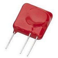
Manufacturer Part Number
TMOV25SP385M
Description
TMOV VARISTOR PB FREE 25S
Manufacturer
Littelfuse Inc
Series
iTMOV®r
Specifications of TMOV25SP385M
Varistor Voltage
682V
Current-surge
20kA
Number Of Circuits
1
Maximum Ac Volts
385VAC
Energy
430J
Package / Case
Disc 25mm 3-Lead
Suppressor Type
Varistor
Peak Surge Current @ 8/20µs
20000A
Varistor Case
25mm DISC
Clamping Voltage Vc Max
1010V
Peak Energy (10/1000us)
430J
Voltage Rating Vdc
682V
Voltage Rating Vac
385V
Lead Free Status / RoHS Status
Lead free / RoHS Compliant
Maximum Dc Volts
-
Lead Free Status / Rohs Status
Lead free / RoHS Compliant


Specifications are subject to change without notice.
Please refer to www.littelfuse.com for current information.
©2009 Littelfuse, Inc.
Nominal Disc
Diameter–mm
Varistor Construction
The process of fabricating a Littelfuse Varistor is illustrated
in the flow chart of Figure 7 . The starting material may
differ in the composition of the additive oxides, in order to
cover the voltage range of product.
Device characteristics are determined at the pressing
operation. The powder is pressed into a form of predeter-
mined thickness in order to obtain a desired value of nomi-
nal voltage. To obtain the desired ratings of peak current
and energy capability, the electrode area and mass of the
device are varied. The range of diameters obtainable in disc
product offerings is listed here:
Of course, other shapes, such as rectangles, are also
possible by simply changing the press dies. Other ceramic
fabrication techniques can be used to make different
shapes. For example, rods or tubes are made by extruding
and cutting to length. After forming, the green (i.e., unfired)
parts are placed in a kiln and sintered at peak temperatures
in excess of 1200ºC. The B ismuth oxide is molten above
825ºC, assisting in the initial densification of the polycrys-
talline ceramic. At higher temperatures, grain growth oc-
curs, forming a structure with controlled grain size.
Electroding is accomplished, for radial and chip devices, by
means of thick film silver fired onto the ceramic surface.
Wire leads or strap terminals are then soldered in place. A
conductive epoxy is used for connecting leads to the axial
3mm discs. For the larger industrial devices (40mm and
60mm diameter discs) the contact material is arc sprayed
Aluminum, with an overspray of Copper if necessary to
give a solderable surface.
FIGURE 7. SCHEMATIC FLOW DIAGRAM OF LITTELFUSE
ENCAPSULATE
MECHANICAL
ELECTRODE
ASSEMBLY
POWDER
MIXING
SINTER
PRESS
ZnO
VARISTOR FABRICATION
ADDITIVE OXIDES
FINAL PRODUCT TO
ELECTRICAL TEST
3
(MAINLY BL
5
7
2
0
3
)
10
FORM CERAMIC BODY
PACKAGE AS/IF REQUIRED
POWDER PREPARATION
14
20
32
Varistor Products
34
40
Revision: November 5, 2009
62
13
Leadless Surface
FIGURE 9A. CROSS-SECTION
OF MA SERIES
Many encapsulation techniques are used in the assembly
of the various Littelfuse Varistor packages. Most radials
and some industrial devices (HA Series) are epoxy coated
in a fluidized bed, whereas epoxy is “spun” onto the axial
device.
Radials are also available with phenolic coatings applied
using a wet process. The PA Series package consists of
plastic molded around a 20mm disc subassembly. The RA,
DA and DB Series devices are all similar in that they all are
composed of discs or chips, with tabs or leads, encased
in a molded plastic shell filled with epoxy. Different pack-
age styles allow variation in energy ratings, as well as in
mechanical mounting.
Figure 9A, 9B and 9C (next page) show construction details
of some Littelfuse varistor packages. Dimensions of the
ceramic, by package type, are above in Table 2.
Industrial Discs
Radial Leaded
Axial Leaded
Boxed, Low
Industrial
Packages
PACKAGE
Mount
Profile
TYPE
TABLE 2. BY–TYPE CERAMIC DIMENSIONS
CH, AUML†, ML†,
TMOV25S
TMOV
BA, BB Series
HA, HB Series
HC, HF Series
,UltraMOV™,
DA, DB Series
MLE†, MLN†
ZA, LA, C–III,
DHB Series
MA Series
HG Series
RA Series
CA Series
SERIES
Series
®
, i TMOV
®
Series
FIGURE 9B. CROSS-SECTION
OF RADIAL LEAD PACKAGE
®
5mm x 8mm Chip, 0603,
14mm, 20mm Diameter
32mm, 40mm Diameter
CERAMIC DIMENSIONS
0805, 1206, 1210, 1812,
60mm Diameter Discs
5mm x 8mm, 10mm x
Disc, 40mm Diameter
Disc, 60mm Diameter
16mm, 14 x 22 Chips
3mm Diameter Disc
5mm, 7mm, 10mm,
Disc, 34mm Square
Discs
2220
Disc
Related parts for TMOV25SP385M
Image
Part Number
Description
Manufacturer
Datasheet
Request
R

Part Number:
Description:
FUSEHOLDER 20A MINI INLINE CRIMP
Manufacturer:
Littelfuse Inc
Datasheet:

Part Number:
Description:
FUSEHOLDER BODY ATO INLINE PNLMT
Manufacturer:
Littelfuse Inc
Datasheet:

Part Number:
Description:
FUSE 2A 63V FAST 1206
Manufacturer:
Littelfuse Inc
Datasheet:
Part Number:
Description:
FUSE 1.25A 63V FAST 1206
Manufacturer:
Littelfuse Inc
Datasheet:
Part Number:
Description:
FUSE .250A 125V FAST 1206
Manufacturer:
Littelfuse Inc
Datasheet:
Part Number:
Description:
FUSE 4A 32V FAST 1206
Manufacturer:
Littelfuse Inc
Datasheet:
Part Number:
Description:
FUSE 1.75A 63V FAST 1206
Manufacturer:
Littelfuse Inc
Datasheet:

Part Number:
Description:
FUSE 1A 32V FST 0603 LEADFREE TR
Manufacturer:
Littelfuse Inc
Datasheet:

Part Number:
Description:
FUSE 1A 32V FAST SLIM 0402
Manufacturer:
Littelfuse Inc
Datasheet:

Part Number:
Description:
FUSE 2A 125V FAST NANO2 SMD
Manufacturer:
Littelfuse Inc
Datasheet:

Part Number:
Description:
FUSE .250A 125V FAST NANO2 SMD
Manufacturer:
Littelfuse Inc
Datasheet:

Part Number:
Description:
FUSE .500A 125V FAST NANO2 SMD
Manufacturer:
Littelfuse Inc
Datasheet:

Part Number:
Description:
FUSE 1.5A 125V FAST NANO2 SMD
Manufacturer:
Littelfuse Inc
Datasheet:

Part Number:
Description:
FUSE 4A 125V FAST NANO2 SMD
Manufacturer:
Littelfuse Inc
Datasheet:

Part Number:
Description:
FUSE 1A 125V FAST NANO2 SMD
Manufacturer:
Littelfuse Inc
Datasheet: