TMOV25SP385M Littelfuse Inc, TMOV25SP385M Datasheet - Page 18
TMOV25SP385M
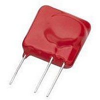
Manufacturer Part Number
TMOV25SP385M
Description
TMOV VARISTOR PB FREE 25S
Manufacturer
Littelfuse Inc
Series
iTMOV®r
Specifications of TMOV25SP385M
Varistor Voltage
682V
Current-surge
20kA
Number Of Circuits
1
Maximum Ac Volts
385VAC
Energy
430J
Package / Case
Disc 25mm 3-Lead
Suppressor Type
Varistor
Peak Surge Current @ 8/20µs
20000A
Varistor Case
25mm DISC
Clamping Voltage Vc Max
1010V
Peak Energy (10/1000us)
430J
Voltage Rating Vdc
682V
Voltage Rating Vac
385V
Lead Free Status / RoHS Status
Lead free / RoHS Compliant
Maximum Dc Volts
-
Lead Free Status / Rohs Status
Lead free / RoHS Compliant


FIGURE 9C. PICTORIAL VIEW OF HIGH ENERGY
DA, DB AND BA/BB SERIES
BA/BB SERIES
DA SERIES
DB SERIES
Revision: November 5, 2009
Varistor Products
14
Turning now to the high current upturn region in Figure 10,
we see that the V-I behavior approaches an ohmic char-
acteristic. The limiting resistance value depends upon the
electrical conductivity of the body of the semiconducting
ZnO grains, which have carrier concentrations in the range
of 10
below 0.3Ωcm.
Varistor electrical characteristics are conveniently displayed
using log-log format in order to show the wide range of
the V-I curve. The log format also is clearer than a linear
representation which tends to exaggerate the nonlinearity
in proportion to the current scale chosen. A typical V-I
Electrical Characterization Varistor V-I Characteristics
characteristic curve is shown in Figure 10. This plot shows
a wider range of current than is normally provided on varis-
tor data sheets in order to illustrate three distinct regions
of electrical operation.
Equivalent Circuit Model
An electrical model for the varistor can be represented by
the simplified equivalent circuit of Figure 11.
FIGURE 10. TYPICAL VARISTOR V-I CURVE PLOTTED ON
1000
500
200
100
FIGURE 11. VARISTOR EQUIVALENT CIRCUIT MODEL
50
20
10
17
10
(0.002μF)
to 10
-8
LEAKAGE
REGION
18
C
10
LOG-LOG SCALE
per cm
-6
SLOPE =
3
10
. This would put the ZnO resistivity
-4
Please refer to www.littelfuse.com for current information.
NORMAL VARISTOR
CURRENT (A)
-- -
1
Specifications are subject to change without notice.
10
R
L
(1Ω)
V
R
(0 TO
ON
OPERATION
-2
x
(TYPICAL V130LA20A)
(LEAD
INDUCTANCE)
∞
)
(TYPICAL V130LA20A)
10
0
R
(1000MΩ)
I = kV
OFF
10
2
©2009 Littelfuse, Inc.
UPTURN
REGION
10
4
Related parts for TMOV25SP385M
Image
Part Number
Description
Manufacturer
Datasheet
Request
R

Part Number:
Description:
FUSEHOLDER 20A MINI INLINE CRIMP
Manufacturer:
Littelfuse Inc
Datasheet:

Part Number:
Description:
FUSEHOLDER BODY ATO INLINE PNLMT
Manufacturer:
Littelfuse Inc
Datasheet:

Part Number:
Description:
FUSE 2A 63V FAST 1206
Manufacturer:
Littelfuse Inc
Datasheet:
Part Number:
Description:
FUSE 1.25A 63V FAST 1206
Manufacturer:
Littelfuse Inc
Datasheet:
Part Number:
Description:
FUSE .250A 125V FAST 1206
Manufacturer:
Littelfuse Inc
Datasheet:
Part Number:
Description:
FUSE 4A 32V FAST 1206
Manufacturer:
Littelfuse Inc
Datasheet:
Part Number:
Description:
FUSE 1.75A 63V FAST 1206
Manufacturer:
Littelfuse Inc
Datasheet:

Part Number:
Description:
FUSE 1A 32V FST 0603 LEADFREE TR
Manufacturer:
Littelfuse Inc
Datasheet:

Part Number:
Description:
FUSE 1A 32V FAST SLIM 0402
Manufacturer:
Littelfuse Inc
Datasheet:

Part Number:
Description:
FUSE 2A 125V FAST NANO2 SMD
Manufacturer:
Littelfuse Inc
Datasheet:

Part Number:
Description:
FUSE .250A 125V FAST NANO2 SMD
Manufacturer:
Littelfuse Inc
Datasheet:

Part Number:
Description:
FUSE .500A 125V FAST NANO2 SMD
Manufacturer:
Littelfuse Inc
Datasheet:

Part Number:
Description:
FUSE 1.5A 125V FAST NANO2 SMD
Manufacturer:
Littelfuse Inc
Datasheet:

Part Number:
Description:
FUSE 4A 125V FAST NANO2 SMD
Manufacturer:
Littelfuse Inc
Datasheet:

Part Number:
Description:
FUSE 1A 125V FAST NANO2 SMD
Manufacturer:
Littelfuse Inc
Datasheet: