TMOV25SP385M Littelfuse Inc, TMOV25SP385M Datasheet - Page 12
TMOV25SP385M
Manufacturer Part Number
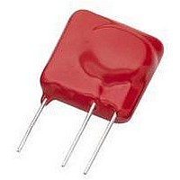
TMOV25SP385M
Description
TMOV VARISTOR PB FREE 25S
Manufacturer
Littelfuse Inc
Series
iTMOV®r
Specifications of TMOV25SP385M
Varistor Voltage
682V
Current-surge
20kA
Number Of Circuits
1
Maximum Ac Volts
385VAC
Energy
430J
Package / Case
Disc 25mm 3-Lead
Suppressor Type
Varistor
Peak Surge Current @ 8/20µs
20000A
Varistor Case
25mm DISC
Clamping Voltage Vc Max
1010V
Peak Energy (10/1000us)
430J
Voltage Rating Vdc
682V
Voltage Rating Vac
385V
Lead Free Status / RoHS Status
Lead free / RoHS Compliant
Maximum Dc Volts
-
Lead Free Status / Rohs Status
Lead free / RoHS Compliant


•
•
•
•
•
•
•
•
•
Transient Voltage Scenarios
ESD (Electrostatic Discharge)
Electrostatic discharge is characterized by very fast rise
times and very high peak voltages and currents. This
energy is the result of an imbalance of positive and
negative charges between objects.
Below are some examples of the voltages which can be
generated, depending on the relative humidity (RH):
Referring to Table 2 on the previous page, it can be
seen that ESD that is generated by everyday activities
can far surpass the vulnerability threshold of standard
semiconductor technologies. Figure 2 shows the
ESD waveform as defined in the IEC 61000-4-2 test
specification.
Inductive Load Switching
The switching of inductive loads generates high energy
transients which increase in magnitude with increasingly
heavy loads. When the inductive load is switched off, the
collapsing magnetic field is converted into electrical energy
which takes the form of a double exponential transient.
Depending on the source, these transients can be as large
as hundreds of volts and hundreds of Amps, with duration
times of 400ms.
Typical sources of inductive transients are:
These examples are extremely common in electrical and
electronic systems. Because the sizes of the loads vary
according to the application, the wave shape, duration,
peak current and peak voltage are all variables which
exist in real world transients. Once these variables can be
approximated, a suitable suppressor technology can be
selected.
Walking across a carpet:
35kV @ RH = 20%; 1.5kV @ RH = 65%
Walking across a vinyl floor:
12kV @ RH = 20%; 250V @ RH = 65%
Worker at a bench:
6kV @ RH = 20%; 100V @ RH = 65%
Vinyl envelopes:
7kV @ RH = 20%; 600V @ RH = 65%
Poly bag picked up from desk:
20kV @ RH = 20%; 1.2kV @ RH = 65%
Generator
Motor
Relay
Transformer
Revision: November 5, 2009
Varistor Products
8
Figure 3. Automotive Load Dump
Figure 4. Cloud-to-Cloud Lightning Strike
Figure 3, shows a transient which is the result of stored
energy within the alternator of an automobile charging
system. A similar transient can also be caused by other
DC motors in a vehicle. For example, DC motors power
amenities such as power locks, seats and windows.
These various applications of a DC motor can produce
transients that are just as harmful to the sensitive
electronic components as transients created in the external
environment.
Lightning Induced Transients
Even though a direct strike is clearly destructive, transients
induced by lightning are not the result of a direct strike.
When a lightning strike occurs, the event creates a
magnetic field which can induce transients of large
magnitude in nearby electrical cables.
Figure 4, shows how a cloud-to-cloud strike will effect
not only ove RHead cables, but also buried cables. Even a
strike 1 mile distant (1.6km) can generate 70V in electrical
cables.
Transient Generated:
• 70 V at 1.6km (1 mile)
• 10 kV at 150m (160 yards)
V
V
S
B
V
10%
V
V
90%
B
B
T = 40ms to 400ms
= 14V
= 25V to 125V
T
1
Please refer to www.littelfuse.com for current information.
Specifications are subject to change without notice.
T
T
R = 0.5Ω to 4Ω
1
= 5ms to 10ms
Buried Line
©2009 Littelfuse, Inc.
t
Related parts for TMOV25SP385M
Image
Part Number
Description
Manufacturer
Datasheet
Request
R

Part Number:
Description:
FUSEHOLDER 20A MINI INLINE CRIMP
Manufacturer:
Littelfuse Inc
Datasheet:

Part Number:
Description:
FUSEHOLDER BODY ATO INLINE PNLMT
Manufacturer:
Littelfuse Inc
Datasheet:

Part Number:
Description:
FUSE 2A 63V FAST 1206
Manufacturer:
Littelfuse Inc
Datasheet:
Part Number:
Description:
FUSE 1.25A 63V FAST 1206
Manufacturer:
Littelfuse Inc
Datasheet:
Part Number:
Description:
FUSE .250A 125V FAST 1206
Manufacturer:
Littelfuse Inc
Datasheet:
Part Number:
Description:
FUSE 4A 32V FAST 1206
Manufacturer:
Littelfuse Inc
Datasheet:
Part Number:
Description:
FUSE 1.75A 63V FAST 1206
Manufacturer:
Littelfuse Inc
Datasheet:

Part Number:
Description:
FUSE 1A 32V FST 0603 LEADFREE TR
Manufacturer:
Littelfuse Inc
Datasheet:

Part Number:
Description:
FUSE 1A 32V FAST SLIM 0402
Manufacturer:
Littelfuse Inc
Datasheet:

Part Number:
Description:
FUSE 2A 125V FAST NANO2 SMD
Manufacturer:
Littelfuse Inc
Datasheet:

Part Number:
Description:
FUSE .250A 125V FAST NANO2 SMD
Manufacturer:
Littelfuse Inc
Datasheet:

Part Number:
Description:
FUSE .500A 125V FAST NANO2 SMD
Manufacturer:
Littelfuse Inc
Datasheet:

Part Number:
Description:
FUSE 1.5A 125V FAST NANO2 SMD
Manufacturer:
Littelfuse Inc
Datasheet:

Part Number:
Description:
FUSE 4A 125V FAST NANO2 SMD
Manufacturer:
Littelfuse Inc
Datasheet:

Part Number:
Description:
FUSE 1A 125V FAST NANO2 SMD
Manufacturer:
Littelfuse Inc
Datasheet: