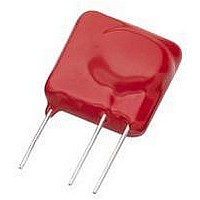
TMOV25SP385M Littelfuse Inc, TMOV25SP385M Datasheet - Page 23

TMOV25SP385M
Manufacturer Part Number
TMOV25SP385M
Description
TMOV VARISTOR PB FREE 25S
Manufacturer
Littelfuse Inc
Series
iTMOV®r
Specifications of TMOV25SP385M
Varistor Voltage
682V
Current-surge
20kA
Number Of Circuits
1
Maximum Ac Volts
385VAC
Energy
430J
Package / Case
Disc 25mm 3-Lead
Suppressor Type
Varistor
Peak Surge Current @ 8/20µs
20000A
Varistor Case
25mm DISC
Clamping Voltage Vc Max
1010V
Peak Energy (10/1000us)
430J
Voltage Rating Vdc
682V
Voltage Rating Vac
385V
Lead Free Status / RoHS Status
Lead free / RoHS Compliant
Maximum Dc Volts
-
Lead Free Status / Rohs Status
Lead free / RoHS Compliant
- Current page: 23 of 212
- Download datasheet (7Mb)
Specifications are subject to change without notice.
Please refer to www.littelfuse.com for current information.
©2009 Littelfuse, Inc.
Three Phase
If only 3 suppressor use 1-GND, 2-GND, 3-GND
For higher voltages use same connections, but
select varistors for the appropriate voltage rating.
If only 3 suppressor use 1-GND, 2-GND, 3-GND
FIGURE 25E. 3 PHASE 120V/208V, 4-WIRE
FIGURE 25C. 3 PHASE 220V, ONE PHASE
FIGURE 25B. 3 PHASE 220V OR 380V,
FIGURE 25A. 3 PHASE 220V/380V,
FIGURE 25F. 3 PHASE 240V/415V
FIGURE 25D. 3 PHASE 220V
240V
1
220V
220V
1
220V
220V
3
3
110V
3
GROUNDED
110V
3
UNGROUNDED
220V
LOWER VOLTAGE
UNGROUNDED
3
220V
3
220V
1
4
1
110V
1
1
4
240V
2
220V
220V
2
2
220V
2
220V
2
2
SUPPRESSOR
CONNECTION
SUPPRESSOR
CONNECTION
SUPPRESSOR
CONNECTION
SUPPRESSOR
CONNECTION
SUPPRESSOR
CONNECTION
SUPPRESSOR
CONNECTION
1 - 2
1 - 3
3 - 2
1 - GND
2 - GND
3 - GND
1 - 2
1 - 3
3 - 2
1 - GND
2 - GND
3 - GND
Varistor Products
1 - 2
2 - 3
1 - 3
1 - 4
2 - 4
3 - 4
1 - 2
2 - 3
3 - 1
1 - 3
1 - 2
2 - 4
3 - 4
Revision: November 5, 2009
19
DC applications require connection between plus and mi-
nus or plus and ground and minus and ground.
For example, if a transient towards ground exists on all
3 phases (common mode transients) only transient
suppressors connected phase to ground would absorb
energy. Transient suppressors connected phase to phase
would not be effective.
On the other hand if a differential mode of transient (phase
to phase) exists then transient suppressors connected
phase to phase would be the correct solution.
This is just a selection of some of the more important varia-
tions in connecting transient suppressors.
The logical approach is to connect the transient suppressor
between the points of the potential difference created by
the transient.The suppressor will then equalize or reduce
these potentials to lower and harmless levels.
DC Application
TRANSIENT
DIFFERENTIAL
COMMON
TRANSIENT
FIGURE 26A. INCORRECT
FIGURE 27A. INCORRECT
MODE
MODE
FIGURE 26. COMMON MODE TRANSIENT
FIGURE 27. DIFFERENTIAL MODE TRANSIENT
AND CORRECT SOLUTION
AND CORRECT SOLUTION
FIGURE 26B. CORRECT
FIGURE 27B. CORRECT
Related parts for TMOV25SP385M
Image
Part Number
Description
Manufacturer
Datasheet
Request
R

Part Number:
Description:
FUSEHOLDER 20A MINI INLINE CRIMP
Manufacturer:
Littelfuse Inc
Datasheet:

Part Number:
Description:
FUSEHOLDER BODY ATO INLINE PNLMT
Manufacturer:
Littelfuse Inc
Datasheet:

Part Number:
Description:
FUSE 2A 63V FAST 1206
Manufacturer:
Littelfuse Inc
Datasheet:

Part Number:
Description:
FUSE 1.25A 63V FAST 1206
Manufacturer:
Littelfuse Inc
Datasheet:

Part Number:
Description:
FUSE .250A 125V FAST 1206
Manufacturer:
Littelfuse Inc
Datasheet:

Part Number:
Description:
FUSE 4A 32V FAST 1206
Manufacturer:
Littelfuse Inc
Datasheet:

Part Number:
Description:
FUSE 1.75A 63V FAST 1206
Manufacturer:
Littelfuse Inc
Datasheet:

Part Number:
Description:
FUSE 1A 32V FST 0603 LEADFREE TR
Manufacturer:
Littelfuse Inc
Datasheet:

Part Number:
Description:
FUSE 1A 32V FAST SLIM 0402
Manufacturer:
Littelfuse Inc
Datasheet:

Part Number:
Description:
FUSE 2A 125V FAST NANO2 SMD
Manufacturer:
Littelfuse Inc
Datasheet:

Part Number:
Description:
FUSE .250A 125V FAST NANO2 SMD
Manufacturer:
Littelfuse Inc
Datasheet:

Part Number:
Description:
FUSE .500A 125V FAST NANO2 SMD
Manufacturer:
Littelfuse Inc
Datasheet:

Part Number:
Description:
FUSE 1.5A 125V FAST NANO2 SMD
Manufacturer:
Littelfuse Inc
Datasheet:

Part Number:
Description:
FUSE 4A 125V FAST NANO2 SMD
Manufacturer:
Littelfuse Inc
Datasheet:

Part Number:
Description:
FUSE 1A 125V FAST NANO2 SMD
Manufacturer:
Littelfuse Inc
Datasheet:


