TMOV25SP385M Littelfuse Inc, TMOV25SP385M Datasheet - Page 11
TMOV25SP385M
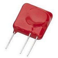
Manufacturer Part Number
TMOV25SP385M
Description
TMOV VARISTOR PB FREE 25S
Manufacturer
Littelfuse Inc
Series
iTMOV®r
Specifications of TMOV25SP385M
Varistor Voltage
682V
Current-surge
20kA
Number Of Circuits
1
Maximum Ac Volts
385VAC
Energy
430J
Package / Case
Disc 25mm 3-Lead
Suppressor Type
Varistor
Peak Surge Current @ 8/20µs
20000A
Varistor Case
25mm DISC
Clamping Voltage Vc Max
1010V
Peak Energy (10/1000us)
430J
Voltage Rating Vdc
682V
Voltage Rating Vac
385V
Lead Free Status / RoHS Status
Lead free / RoHS Compliant
Maximum Dc Volts
-
Lead Free Status / Rohs Status
Lead free / RoHS Compliant


Specifications are subject to change without notice.
Please refer to www.littelfuse.com for current information.
Introduction to Overvoltage Suppression
©2009 Littelfuse, Inc.
Lighting
Switching
EMP
ESD
Figure 1. Lightning Transient Waveform
Table 1. Examples of transient sources and magnitude
Transient Threats – What Are Transients?
Voltage transients are defined as short duration surges of
electrical energy and are the result of the sudden release
of energy that was previously stored, or induced by other
means, such as heavy inductive loads or lightning strikes.
In electrical or electronic circuits, this energy can be
released in a predictable manner via controlled switching
actions, or randomly induced into a circuit from external
sources.
Repeatable transients are frequently caused by the
operation of motors, generators, or the switching of
reactive circuit components. Random transients, on the
other hand, are often caused by Lightning (Figure 1) and
Electrostatic Discharge (ESD) (Figure 2). Lightning and ESD
generally occur unpredictably, and may require elaborate
monitoring to be accurately measured, especially if induced
at the circuit board level. Numerous electronics standards
groups have analyzed transient voltage occurrences
using accepted monitoring or testing methods. The key
characteristics of several transients are shown below in
Table 1.
Characteristics of Transient Voltage Spikes
Transient voltage spikes generally exhibit a "double
exponential" wave form, shown in Figure 1 for lightning and
figure 2 for ESD. The exponential rise time of lightning is in
the range 1.2μs to 10μs (essentially 10% to 90%) and the
duration is in the range of 50μs to 1000μs (50% of peak
values). ESD on the other hand, is a much shorter duration
event. The rise time has been characterized at less than 1
ns. The overall duration is approximately 100ns.
t1
Vp
t2
VOLTAGE
600V
25kV
15kV
1kV
Vp/2
CURRENT
500A
20kA
10A
30A
RISE-TIME DURATION
<1ns
10μs
50μs
20ns
Varistor Products
500ms
100ns
1ms
1ms
Revision: November 5, 2009
t
7
Figure 2. ESD Test Waveform
Table 2: Range of device vulnerability.
Why are Transients of Increasing Concern?
Component miniaturization has resulted in increased
sensitivity to electrical stresses. Microprocessors for
example, have structures and conductive paths which
are unable to handle high currents from ESD transients.
Such components operate at very low voltages, so
voltage disturbances must be controlled to prevent device
interruption and latent or catastrophic failures. Sensitive
devices such as microprocessors are being adopted at
an exponential rate. Microprocessors are beginning to
perform transparent operations never before imagined.
Everything from home appliances, such as dishwashers, to
industrial controls and even toys, have increased the use of
microprocessors to improve functionality and efficiency.
Vehicles now employ many electronics systems to
control the engine, climate, braking and, in some cases,
steering systems. Some of the innovations are designed
to improve efficiency, but many are safety related, such as
ABS and traction control systems. Many of the features in
appliances and automobiles use modules which present
transient threats (such as electric motors). Not only is
the general environment hostile, but the equipment or
appliance can also be sources of threats. For this reason,
careful circuit design and the correct use of overvoltage
protection technology will greatly improve the reliability
and safety of the end application. Table 2 shows the
vulnerability of various component technologies.
t
r
100
I
I
90
30
60
= 0.7 to 1.0ns
%
Bipolar Transistors
Schottky Diodes
Device Type
GaAsFET
MOSFET
EPROM
VMOS
CMOS
JFET
SCR
30n
60n
Vulnerability (volts)
140-7000
250-3000
300-2500
380-7000
680-1000
30-1800
100-200
100-300
100
Related parts for TMOV25SP385M
Image
Part Number
Description
Manufacturer
Datasheet
Request
R

Part Number:
Description:
FUSEHOLDER 20A MINI INLINE CRIMP
Manufacturer:
Littelfuse Inc
Datasheet:

Part Number:
Description:
FUSEHOLDER BODY ATO INLINE PNLMT
Manufacturer:
Littelfuse Inc
Datasheet:

Part Number:
Description:
FUSE 2A 63V FAST 1206
Manufacturer:
Littelfuse Inc
Datasheet:
Part Number:
Description:
FUSE 1.25A 63V FAST 1206
Manufacturer:
Littelfuse Inc
Datasheet:
Part Number:
Description:
FUSE .250A 125V FAST 1206
Manufacturer:
Littelfuse Inc
Datasheet:
Part Number:
Description:
FUSE 4A 32V FAST 1206
Manufacturer:
Littelfuse Inc
Datasheet:
Part Number:
Description:
FUSE 1.75A 63V FAST 1206
Manufacturer:
Littelfuse Inc
Datasheet:

Part Number:
Description:
FUSE 1A 32V FST 0603 LEADFREE TR
Manufacturer:
Littelfuse Inc
Datasheet:

Part Number:
Description:
FUSE 1A 32V FAST SLIM 0402
Manufacturer:
Littelfuse Inc
Datasheet:

Part Number:
Description:
FUSE 2A 125V FAST NANO2 SMD
Manufacturer:
Littelfuse Inc
Datasheet:

Part Number:
Description:
FUSE .250A 125V FAST NANO2 SMD
Manufacturer:
Littelfuse Inc
Datasheet:

Part Number:
Description:
FUSE .500A 125V FAST NANO2 SMD
Manufacturer:
Littelfuse Inc
Datasheet:

Part Number:
Description:
FUSE 1.5A 125V FAST NANO2 SMD
Manufacturer:
Littelfuse Inc
Datasheet:

Part Number:
Description:
FUSE 4A 125V FAST NANO2 SMD
Manufacturer:
Littelfuse Inc
Datasheet:

Part Number:
Description:
FUSE 1A 125V FAST NANO2 SMD
Manufacturer:
Littelfuse Inc
Datasheet: