TMOV25SP385M Littelfuse Inc, TMOV25SP385M Datasheet - Page 15
TMOV25SP385M
Manufacturer Part Number
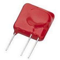
TMOV25SP385M
Description
TMOV VARISTOR PB FREE 25S
Manufacturer
Littelfuse Inc
Series
iTMOV®r
Specifications of TMOV25SP385M
Varistor Voltage
682V
Current-surge
20kA
Number Of Circuits
1
Maximum Ac Volts
385VAC
Energy
430J
Package / Case
Disc 25mm 3-Lead
Suppressor Type
Varistor
Peak Surge Current @ 8/20µs
20000A
Varistor Case
25mm DISC
Clamping Voltage Vc Max
1010V
Peak Energy (10/1000us)
430J
Voltage Rating Vdc
682V
Voltage Rating Vac
385V
Lead Free Status / RoHS Status
Lead free / RoHS Compliant
Maximum Dc Volts
-
Lead Free Status / Rohs Status
Lead free / RoHS Compliant


Specifications are subject to change without notice.
Please refer to www.littelfuse.com for current information.
©2009 Littelfuse, Inc.
Varistor Microstructure
The bulk of the varistor between contacts is comprised of
ZnO grains of an average size "d" as shown in the schemat-
ic model of Figure 3. Resistivity of the ZnO is <0.3 Ω–cm.
Designing a varistor for a given nominal varistor voltage,
(V
such that the appropriate number of grains, (n), are in se-
ries between electrodes. In practice, the varistor material is
characterized by a voltage gradient measured across its
thickness by a specific volts/mm value. By controlling
composition and manufacturing conditions the gradient
remains fixed. Because there are practical limits to the
range of thicknesses achievable, more than one voltage
gradient value is desired. By altering the composition of
the metal oxide additives it is possible to change the grain
size "d" and achieve the desired result.
A fundamental property of the ZnO varistor is that the
voltage drop across a single interface "junction" between
grains is nearly constant. Observations over a range of
compositional variations and processing conditions show a
fixed voltage drop of about 2V-3V per grain boundary
junction. Also, the voltage drop does not vary for grains of
different sizes. It follows, then, that the varistor voltage
will be determined by the thickness of the material and the
size of the ZnO grains. The relationship can be stated very
simply as follows:
and, varistor thickness, D = (n + 1)d
where,
FIGURE 3.
N
), is basically a matter of selecting the device thickness
SCHEMATIC DEPICTION OF THE
MICROSTRUCTURE OF A METAL-OXIDE
VARISTOR, GRAINS OF CONDUCTING
ZnO (AVERAGE SIZE d) ARE SEPARATED
BY INTERGRANULAR BOUNDARIES.
R
CURRENT
X
=
V
--- -
I
d = average grain size
≈
between electrodes
ELECTRODES
INTERGRANULAR
BOUNDARY
V
---------------- -
N
3
×
d
d
Varistor Products
Revision: November 5, 2009
11
The varistor voltage, (V
varistor at the point on its V-I characteristic where the
transition (v) is complete from the low-level linear region
to the highly nonlinear region. For standard measurement
purposes, it is arbitrarily defined as the voltage at a current
of 1mA. Some typical values of dimensions for Littelfuse
Varistors are given in Table 1.
NOTE: Low voltage formulation.
Theory of Operation
Because of the polycrystalline nature of metal-oxide semi-
conductor varistors, the physical operation of the device is
more complex than that of conventional semiconductors.
Intensive measurement has determined many of the de-
vice’s electrical characteristics, and much effort continues
to better define the varistor’s operation. However from the
user’s viewpoint, this is not nearly as important as under-
standing the basic electrical properties as they relate to
device construction.
The key to explaining metal-oxide varistor operation lies in
understanding the electronic phenomena occurring near
the grain boundaries, or junctions between the Z
While some of the early theory supposed that electronic
tunneling occurred through an insulating second phase
layer at the grain boundaries, varistor operation is prob-
ably better described by a series-parallel arrangement of
semiconducting diodes. In this model, the grain boundaries
contain defect states which trap free electrons from the
n-type semiconducting Z
charge depletion layer in the ZnO grains in the region adja-
cent to the grain boundaries. (See reference notes on the
last page of this section).
Evidence for depletion layers in the varistor is shown in Fig-
ure 4, where the inverse of the capacitance per boundary
squared is plotted against the applied voltage per boundary.
This is the same type of behavior observed carrier concen-
tration, N, was determined to be about 2 x 10¹⁷ per cm
addition, the width of the depletion layer was calculated to
be about 1000 Angstrom units. Single junction studies also
support the diode model.
It is these depletion layers that block the free flow of
carriers and are responsible for the low voltage insulating
behavior in the leakage region as depicted in Figure 5. The
leakage current is due to the free flow of carriers across
VARISTOR
VOLTAGE
150V
25V
VOLTS
RMS
RMS
GRAIN SIZE
AVERAGE
MICRONS
80 (Note)
20
N
), is defined as the voltage across a
TABLE 1.
N
O grains, thus forming a space
75
12
n
GRADIENT
V/mm AT
1mA
150
39
THICKNESS
DEVICE
N
mm
1.5
O grains.
1.0
3
. In
Related parts for TMOV25SP385M
Image
Part Number
Description
Manufacturer
Datasheet
Request
R

Part Number:
Description:
FUSEHOLDER 20A MINI INLINE CRIMP
Manufacturer:
Littelfuse Inc
Datasheet:

Part Number:
Description:
FUSEHOLDER BODY ATO INLINE PNLMT
Manufacturer:
Littelfuse Inc
Datasheet:

Part Number:
Description:
FUSE 2A 63V FAST 1206
Manufacturer:
Littelfuse Inc
Datasheet:
Part Number:
Description:
FUSE 1.25A 63V FAST 1206
Manufacturer:
Littelfuse Inc
Datasheet:
Part Number:
Description:
FUSE .250A 125V FAST 1206
Manufacturer:
Littelfuse Inc
Datasheet:
Part Number:
Description:
FUSE 4A 32V FAST 1206
Manufacturer:
Littelfuse Inc
Datasheet:
Part Number:
Description:
FUSE 1.75A 63V FAST 1206
Manufacturer:
Littelfuse Inc
Datasheet:

Part Number:
Description:
FUSE 1A 32V FST 0603 LEADFREE TR
Manufacturer:
Littelfuse Inc
Datasheet:

Part Number:
Description:
FUSE 1A 32V FAST SLIM 0402
Manufacturer:
Littelfuse Inc
Datasheet:

Part Number:
Description:
FUSE 2A 125V FAST NANO2 SMD
Manufacturer:
Littelfuse Inc
Datasheet:

Part Number:
Description:
FUSE .250A 125V FAST NANO2 SMD
Manufacturer:
Littelfuse Inc
Datasheet:

Part Number:
Description:
FUSE .500A 125V FAST NANO2 SMD
Manufacturer:
Littelfuse Inc
Datasheet:

Part Number:
Description:
FUSE 1.5A 125V FAST NANO2 SMD
Manufacturer:
Littelfuse Inc
Datasheet:

Part Number:
Description:
FUSE 4A 125V FAST NANO2 SMD
Manufacturer:
Littelfuse Inc
Datasheet:

Part Number:
Description:
FUSE 1A 125V FAST NANO2 SMD
Manufacturer:
Littelfuse Inc
Datasheet: