TMOV25SP385M Littelfuse Inc, TMOV25SP385M Datasheet - Page 60
TMOV25SP385M
Manufacturer Part Number
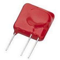
TMOV25SP385M
Description
TMOV VARISTOR PB FREE 25S
Manufacturer
Littelfuse Inc
Series
iTMOV®r
Specifications of TMOV25SP385M
Varistor Voltage
682V
Current-surge
20kA
Number Of Circuits
1
Maximum Ac Volts
385VAC
Energy
430J
Package / Case
Disc 25mm 3-Lead
Suppressor Type
Varistor
Peak Surge Current @ 8/20µs
20000A
Varistor Case
25mm DISC
Clamping Voltage Vc Max
1010V
Peak Energy (10/1000us)
430J
Voltage Rating Vdc
682V
Voltage Rating Vac
385V
Lead Free Status / RoHS Status
Lead free / RoHS Compliant
Maximum Dc Volts
-
Lead Free Status / Rohs Status
Lead free / RoHS Compliant


AUML Varistor Series
Product Dimensions (mm)
A Load Dump transient occurs when the alternator load
in the automobile is abruptly reduced. The worst case
scenario of this transient occurs when the battery is
disconnected while operating at full rated load. There
are a number of different Load Dump specifications in
existence in the automotive industry, with the most
common one being that recommended by the Society of
Automotive Engineers, specification #SAE J1113. Because
of the diversity of these Load Dump specifications
Littelfuse defines the Load Dump energy capability of
Explanation of Terms
Maximum Continuous DC Working Voltage (*V
This is the maximum continuous DC voltage which may
be applied, up to the maximum operating temperature
(125ºC), to the ML suppressor. This voltage is used as the
reference test point for leakage current and is always less
than the breakdown voltage of the device.
Load Dump Energy Rating *W
This is the actual energy the part is rated to dissipate
under Load Dump conditions (not to be confused with the
"source energy" of a Load Dump test specification).
Maximum Clamping Voltage *V
This is the peak voltage appearing across the suppressor
when measured at conditions of specified pulse current
and specified waveform (8/20μs). It is important to note
that the peak current and peak voltage may not necessarily
be coincidental in time.
SYMBOL
D (max.)
W
A
B
C
E
L
Note: Avoid metal runs in this area, parts are not recommended
for use in applications using Silver (Ag) epoxy paste.
Surface Mount Multilayer Varistors (MLVs) > AUML Series
0.020 -/+ 0.010
0.125 -/+ 0.012 3.20 -/+ 0.03
0.060 -/+ 0.011
PAD LAYOUT DIMENSIONS
0.203
0.103
0.065
0.071
IN
1206 Size
1.60 -/+ 0.28
0.50 -/+0.25
5.150
2.620
1.650
MM
1.80
LD +
C +
0.020 -/+ 0.010 0.50 -/+ 0.25 0.020 -/+ 0.010
0.125 -/+ 0.012
0.100 -/+ 0.012
0.073
0.070
0.219
0.147
IN
M*(DC)+ +
1210 Size
Revision: November 5, 2009
Varistor Products
)
3.20 -/+ 0.30 0.180 -/+ 0.014
2.54 -/+ 0.30 0.125 -/+ 0.012
3.730
5.510
1.850
MM
1.80
56
the AUML suppressor range as that energy dissipated by
the device itself, independent of the test circuit setup.
The resultant Load Dump energy handling capability
serves as an excellent figure of merit for the AUML
suppressor. Standard Load Dump specifications require
a device capability of 10 pulses at rated energy, across
a temperature range of -40ºC to +125ºC. This capability
requirement is well within the ratings of all of the AUML
Series (Figure 5).
Leakage Current *I
In the nonconducting mode, the device is at a very
high impedance (approaching 10
voltage) and appears as an almost open circuit in the
system. The leakage current drawn at this level is very
low (<25μA at ambient temperature) and, unlike the
Zener diode, the multilayer TVS has the added advantage
that, when operated up to its maximum temperature,
its leakage current will not increase above 500μA.
Nominal Voltage *V
This is the voltage at which the AUML enters its
conduction state and begins to suppress transients.
In the automotive environment this voltage is
defined at the 10mA point and has a minimum
(V
N(DC) MIN
0.272
0.172
0.073
) and maximum (V
0.07
IN
D
1812 Size
Please refer to www.littelfuse.com/series/AUML.html for current information.
CHIP LAYOUT DIMENSIONS
L +
W
0.50 -/+
4.50 -/+
3.20 -/+
N*DC+ +
4.360
6.910
1.850
MM
1.80
0.25
0.35
0.30
E
N(DC) MAX
Specifications are subject to change without notice.
0.030 -/+ 0.010
0.225 -/+ 0.016
0.197 -/+ 0.016
6
Ω at its rated working
) voltage specified.
0.315
0.240
0.073
0.118
IN
L
2220 Size
0.75 -/+ 0.25
5.70 -/+ 0.40
5.00 -/+ 0.40
©2009 Littelfuse, Inc.
8.000
6.190
1.850
MM
3.00
Related parts for TMOV25SP385M
Image
Part Number
Description
Manufacturer
Datasheet
Request
R

Part Number:
Description:
FUSEHOLDER 20A MINI INLINE CRIMP
Manufacturer:
Littelfuse Inc
Datasheet:

Part Number:
Description:
FUSEHOLDER BODY ATO INLINE PNLMT
Manufacturer:
Littelfuse Inc
Datasheet:

Part Number:
Description:
FUSE 2A 63V FAST 1206
Manufacturer:
Littelfuse Inc
Datasheet:
Part Number:
Description:
FUSE 1.25A 63V FAST 1206
Manufacturer:
Littelfuse Inc
Datasheet:
Part Number:
Description:
FUSE .250A 125V FAST 1206
Manufacturer:
Littelfuse Inc
Datasheet:
Part Number:
Description:
FUSE 4A 32V FAST 1206
Manufacturer:
Littelfuse Inc
Datasheet:
Part Number:
Description:
FUSE 1.75A 63V FAST 1206
Manufacturer:
Littelfuse Inc
Datasheet:

Part Number:
Description:
FUSE 1A 32V FST 0603 LEADFREE TR
Manufacturer:
Littelfuse Inc
Datasheet:

Part Number:
Description:
FUSE 1A 32V FAST SLIM 0402
Manufacturer:
Littelfuse Inc
Datasheet:

Part Number:
Description:
FUSE 2A 125V FAST NANO2 SMD
Manufacturer:
Littelfuse Inc
Datasheet:

Part Number:
Description:
FUSE .250A 125V FAST NANO2 SMD
Manufacturer:
Littelfuse Inc
Datasheet:

Part Number:
Description:
FUSE .500A 125V FAST NANO2 SMD
Manufacturer:
Littelfuse Inc
Datasheet:

Part Number:
Description:
FUSE 1.5A 125V FAST NANO2 SMD
Manufacturer:
Littelfuse Inc
Datasheet:

Part Number:
Description:
FUSE 4A 125V FAST NANO2 SMD
Manufacturer:
Littelfuse Inc
Datasheet:

Part Number:
Description:
FUSE 1A 125V FAST NANO2 SMD
Manufacturer:
Littelfuse Inc
Datasheet: