TMOV25SP385M Littelfuse Inc, TMOV25SP385M Datasheet - Page 77
TMOV25SP385M
Manufacturer Part Number
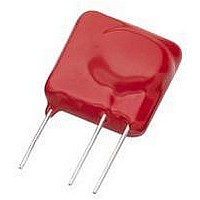
TMOV25SP385M
Description
TMOV VARISTOR PB FREE 25S
Manufacturer
Littelfuse Inc
Series
iTMOV®r
Specifications of TMOV25SP385M
Varistor Voltage
682V
Current-surge
20kA
Number Of Circuits
1
Maximum Ac Volts
385VAC
Energy
430J
Package / Case
Disc 25mm 3-Lead
Suppressor Type
Varistor
Peak Surge Current @ 8/20µs
20000A
Varistor Case
25mm DISC
Clamping Voltage Vc Max
1010V
Peak Energy (10/1000us)
430J
Voltage Rating Vdc
682V
Voltage Rating Vac
385V
Lead Free Status / RoHS Status
Lead free / RoHS Compliant
Maximum Dc Volts
-
Lead Free Status / Rohs Status
Lead free / RoHS Compliant


NOTE: Average power dissipation of transients should not exceed 0.6W
Because the TMOV
Two soldering methods are possible. Firstly, hand soldering: It is recommended to heat-sink the leads of the device. Secondly, wave solder-
ing: It is critically important that all preheat stage and the solder bath temperatures are rigidly controlled.
©2009 Littelfuse, Inc.
Specifications are subject to change without notice.
Please refer to www.littelfuse.com/series/tmov.html for current information.
Repetitive Surge Capability for 14mm Parts
Wave Solder Profile
Non Lead–free Profile
Physical Specifications
Lead Material
Soldering
Characteristics
Insulating Material
Device Labeling
Figure 5
Figure 7
10000
1000
100
10
300
250
200
150
100
1
50
0
10
0
2
1
0.5
®
and iTMOV
10
Non Lead–free parts: Solder coated
Copper wire, or Tin–coated Copper wire
Lead–free parts: Tin–coated Copper wire
Solderability per MIL–STD–202,
Method 208E
Cured, flame retardant epoxy polymer
meets UL94V–0 requirements
Marked with LF , voltage, UL/CSA logos,
and date code
1
100
10
2
1.5
Impulse Duration (μs)
TIME(MINUTES)
®
varistors contain a thermal protection device, care must be taken when soldering the devices into place.
10
3
2
Maximum Wave 240C
10
4
2.5
1000
10
Varistor Products
Model 14 mm
Radial Lead Varistors > TMOV
5
3
10
6
3.5
Revision: November 5, 2009
10000
4
73
NOTE: Average power dissipation of transients should not exceed 1.0W
Operating/Storage
Temperature
Passive Aging
Humidity Aging
Thermal Shock
Solvent Resistance
Moisture Sensitivity
Repetitive Surge Capability for 20mm Parts
Lead–free Profile
Environmental Specifications
Figure 6
Figure 8
10000
1000
100
10
300
250
200
150
100
1
50
0
10
0
2
®
0.5
and iTMOV
1
1
100
10
Impulse Duration (μs)
1.5
TIME(MINUTES)
®
10
-40°C to +85°C
+85°C, 1000 hours
+/-10% typical voltage change
+85°C, 85% RH , 1000 hours
+/-10% typical voltage change
+85°C to -40°C 5 times
+/-10% typical voltage change
MIL–STD–202, Method 215F
Level 1, J–STD–020C
Series
2
Maximum Wave 260C
2
10
TMOV
3
2.5
1000
®
10
and i TMOV
Model 20 mm
4
3
10
5
®
3.5
Varistor Series
10
6
10000
4
Related parts for TMOV25SP385M
Image
Part Number
Description
Manufacturer
Datasheet
Request
R

Part Number:
Description:
FUSEHOLDER 20A MINI INLINE CRIMP
Manufacturer:
Littelfuse Inc
Datasheet:

Part Number:
Description:
FUSEHOLDER BODY ATO INLINE PNLMT
Manufacturer:
Littelfuse Inc
Datasheet:

Part Number:
Description:
FUSE 2A 63V FAST 1206
Manufacturer:
Littelfuse Inc
Datasheet:
Part Number:
Description:
FUSE 1.25A 63V FAST 1206
Manufacturer:
Littelfuse Inc
Datasheet:
Part Number:
Description:
FUSE .250A 125V FAST 1206
Manufacturer:
Littelfuse Inc
Datasheet:
Part Number:
Description:
FUSE 4A 32V FAST 1206
Manufacturer:
Littelfuse Inc
Datasheet:
Part Number:
Description:
FUSE 1.75A 63V FAST 1206
Manufacturer:
Littelfuse Inc
Datasheet:

Part Number:
Description:
FUSE 1A 32V FST 0603 LEADFREE TR
Manufacturer:
Littelfuse Inc
Datasheet:

Part Number:
Description:
FUSE 1A 32V FAST SLIM 0402
Manufacturer:
Littelfuse Inc
Datasheet:

Part Number:
Description:
FUSE 2A 125V FAST NANO2 SMD
Manufacturer:
Littelfuse Inc
Datasheet:

Part Number:
Description:
FUSE .250A 125V FAST NANO2 SMD
Manufacturer:
Littelfuse Inc
Datasheet:

Part Number:
Description:
FUSE .500A 125V FAST NANO2 SMD
Manufacturer:
Littelfuse Inc
Datasheet:

Part Number:
Description:
FUSE 1.5A 125V FAST NANO2 SMD
Manufacturer:
Littelfuse Inc
Datasheet:

Part Number:
Description:
FUSE 4A 125V FAST NANO2 SMD
Manufacturer:
Littelfuse Inc
Datasheet:

Part Number:
Description:
FUSE 1A 125V FAST NANO2 SMD
Manufacturer:
Littelfuse Inc
Datasheet: