101-1279 Rabbit Semiconductor, 101-1279 Datasheet - Page 48
101-1279
Manufacturer Part Number
101-1279
Description
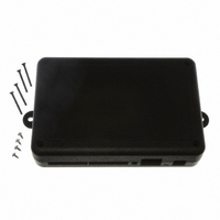
PLASTIC ENCLOSURE FOR BL4S100
Manufacturer
Rabbit Semiconductor
Datasheet
1.20-101-1258.pdf
(144 pages)
Specifications of 101-1279
Accessory Type
Enclosure
Product
Prototyping Accessories
Processor Type
BL4S100
Board Size
146 mm x 96 mm x 16 mm
Interface Type
Ethernet
For Use With/related Products
BL4S100
Lead Free Status / RoHS Status
Not applicable / Not applicable
Other names
316-1159


•
•
•
•
4.2.4 Real-Time Clock
If you plan to use the real-time clock functionality in your application, you will need to set
the real-time clock. You may set the real-time clock using the SETRTCKB.C sample pro-
gram from the Dynamic C SAMPLES\RTCLOCK folder. The RTC_TEST.C sample pro-
gram in the Dynamic C SAMPLES\RTCLOCK folder provides additional examples of how
to read and set the real-time clock
4.2.5 TCP/IP Sample Programs
TCP/IP sample programs are described in Chapter 5.
4.2.6 ZigBee Sample Programs
ZigBee sample programs are described in Chapter 6.
BL4S100 User’s Manual
ADC_RD_CALDATA.C
gain and offset, in the Dynamic C
operation.
ADC_RD_DIFF.C
ues for a differential A/D converter channel using calibration coefficients previously
stored in the user block. The user selects to display either the raw data or the voltage
equivalent.
Once you compile and run this sample program, connect the power supply across a
differential channel pair, then follow the instructions in the Dynamic C
ADC_RD_MA.C
for a milli-amp A/D converter channel using calibration coefficients previously stored
in the user block.
Before you compile and run this sample program, jumper pins 1–2 and 5–6 on headers
J10 and J11. Then connect a current meter in series with the power supply connected to
one of pins AIN0–AIN3 and AGND, then compile and run the sample program, and
follow the instructions in the Dynamic C
the power supply.
ADC_RD_SE_UNIPOLAR.C
single-ended analog input channels using calibration coefficients previously stored in
the user block.
Before you compile and run this sample program, connect the power supply (which
should be OFF) between a pin (AIN0–AIN7) and AGND, then compile and run the
sample program, and follow the instructions in the Dynamic C
voltage readings will be displayed for all the channels measured to that point.
—Demonstrates how to read and display voltage and equivalent values
—Demonstrates how to read and display voltage and equivalent val-
—Demonstrates how to display the two calibration coefficients,
—Demonstrates how to read and display the voltage of all
STDIO
STDIO
window for each channel and mode of
window as you vary the output from
STDIO
window. The
STDIO
window.
46
Related parts for 101-1279
Image
Part Number
Description
Manufacturer
Datasheet
Request
R

Part Number:
Description:
COMPUTER SNGLBD BL2120 FRCTNLOCK
Manufacturer:
Rabbit Semiconductor
Datasheet:

Part Number:
Description:
KIT APPLCTN RABBITCORE RCM4010
Manufacturer:
Rabbit Semiconductor
Datasheet:

Part Number:
Description:
KIT MESH NETWORK ADD-ON RCM4510W
Manufacturer:
Rabbit Semiconductor
Datasheet:

Part Number:
Description:
KIT DEV FOR BL2500 COYOTE
Manufacturer:
Rabbit Semiconductor
Datasheet:

Part Number:
Description:
KIT APPLICATION SIMPLE SENSOR
Manufacturer:
Rabbit Semiconductor
Datasheet:


Part Number:
Description:
PWR SUPPLY UNIV 110/240VAC-12VDC
Manufacturer:
Rabbit Semiconductor

Part Number:
Description:
IC CPU RABBIT2000 30MHZ 100PQFP
Manufacturer:
Rabbit Semiconductor
Datasheet:

Part Number:
Description:
IC CPU RABBIT4000 128-LQFP
Manufacturer:
Rabbit Semiconductor
Datasheet:
Part Number:
Description:
IC MPU RABIT3000A 55.5MHZ128LQFP
Manufacturer:
Rabbit Semiconductor
Datasheet:

Part Number:
Description:
MODULE RABBITCORE RCM4010
Manufacturer:
Rabbit Semiconductor
Datasheet:

Part Number:
Description:
RCM4110 RABBITCORE
Manufacturer:
Rabbit Semiconductor
Datasheet:

Part Number:
Description:
MODULE RABBITCORE RCM2000
Manufacturer:
Rabbit Semiconductor
Datasheet:

Part Number:
Description:
MODULE RABBITCORE RCM3000
Manufacturer:
Rabbit Semiconductor
Datasheet:

Part Number:
Description:
MCU RCM4000 RABBITCORE
Manufacturer:
Rabbit Semiconductor
Datasheet: