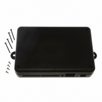
101-1279 Rabbit Semiconductor, 101-1279 Datasheet - Page 42

101-1279
Manufacturer Part Number
101-1279
Description
PLASTIC ENCLOSURE FOR BL4S100
Manufacturer
Rabbit Semiconductor
Datasheet
1.20-101-1258.pdf
(144 pages)
Specifications of 101-1279
Accessory Type
Enclosure
Product
Prototyping Accessories
Processor Type
BL4S100
Board Size
146 mm x 96 mm x 16 mm
Interface Type
Ethernet
For Use With/related Products
BL4S100
Lead Free Status / RoHS Status
Not applicable / Not applicable
Other names
316-1159
- Current page: 42 of 144
- Download datasheet (3Mb)
Rabbit recommends that you run and understand both the
CAPTURE.C
CAPTURE_IRQ.C
•
•
BL4S100 User’s Manual
Once the connections have been made, compile and run this sample program. Change
the offset and duty cycle for a given PPM channel via the Dynamic C
and watch the change to the begin and end counts measured on the input capture inputs.
The PPM frequency can be changed in the
PULSE_CAPTURE_IRQ.C
method using RIO interrupts.
IN0 is configured as the pulse capture input, and OUT0–
OUT7 are configured as PWM outputs of varying fre-
quencies and duty cycles that provide signals to test the
capture with. Connect IN0 and OUT0 together.
If an external signal source is available, connect it to
IN0 for capture.
If an external signal source is not available, connect IN0 on the BL4S100 to SW1.
Once you compile and run this sample program, press any key on your PC keyboard to
pause or unpause the display—the capture will continue in the background. Change the
IN0 connection to any of OUT0–OUT7 or an external source to capture a different signal.
This sample program will continuously capture single pulses in an interrupt service
request for display
PWM.C
OUT0–OUT7. The PWM signals are set for a frequency of 200 Hz with the duty cycle
adjustable from 0 to 100% by the user. These pins can be connected to an oscilloscope
to view the waveform being generated. The overall frequency can be adjusted in the
#define PWM_FREQ
Once you compile and run the sample program, change the duty cycle for a given PWM
output channel via the Dynamic C
on the oscilloscope. Signals on the same RIO counter block (OUT0 and OUT1 for
example) will all be synchronized with each other. Different blocks may have a phase
shift from each other, but will run at the same frequency.
Global synchronization can be used to synchronize different block on the RIO, but this
is not demonstrated in this sample program.
1. The digital outputs on the BL4S100 do not have an internal pull-up resistor and will not register on
2. Connect the oscilloscope probe to digital output pins OUT0–OUT3 on headers J3 or J4. Remember
the oscilloscope without a pull-up resistor. The Demonstration Board has pull-up resistors—
connect OUT0–OUT3 on the BL4S100 to SW1–SW4 on header J1 of the Demonstration Board.
to connect the oscilloscope ground to GND on header J4.
—Demonstrates the use of the eight PWM channels on digital output pins
sample programs before looking at
uses concepts covered in the simpler sample programs.
line. Follow these instructions when running this sample program.
—Demonstrates the use of an advanced pulse capture
STDIO
window and watch the change in waveforms
#define PPM_FREQ
PULSE_CAPTURE_IRQ.C
INTERRUPTS.C
line.
since
STDIO
and the
PULSE_
window
PULSE_
40
Related parts for 101-1279
Image
Part Number
Description
Manufacturer
Datasheet
Request
R

Part Number:
Description:
COMPUTER SNGLBD BL2120 FRCTNLOCK
Manufacturer:
Rabbit Semiconductor
Datasheet:

Part Number:
Description:
KIT APPLCTN RABBITCORE RCM4010
Manufacturer:
Rabbit Semiconductor
Datasheet:

Part Number:
Description:
KIT MESH NETWORK ADD-ON RCM4510W
Manufacturer:
Rabbit Semiconductor
Datasheet:

Part Number:
Description:
KIT DEV FOR BL2500 COYOTE
Manufacturer:
Rabbit Semiconductor
Datasheet:

Part Number:
Description:
KIT APPLICATION SIMPLE SENSOR
Manufacturer:
Rabbit Semiconductor
Datasheet:

Part Number:
Description:
PWR SUPPLY UNIV 110/240VAC-12VDC
Manufacturer:
Rabbit Semiconductor

Part Number:
Description:
IC CPU RABBIT2000 30MHZ 100PQFP
Manufacturer:
Rabbit Semiconductor
Datasheet:

Part Number:
Description:
IC CPU RABBIT4000 128-LQFP
Manufacturer:
Rabbit Semiconductor
Datasheet:

Part Number:
Description:
IC MPU RABIT3000A 55.5MHZ128LQFP
Manufacturer:
Rabbit Semiconductor
Datasheet:

Part Number:
Description:
MODULE RABBITCORE RCM4010
Manufacturer:
Rabbit Semiconductor
Datasheet:

Part Number:
Description:
RCM4110 RABBITCORE
Manufacturer:
Rabbit Semiconductor
Datasheet:

Part Number:
Description:
MODULE RABBITCORE RCM2000
Manufacturer:
Rabbit Semiconductor
Datasheet:

Part Number:
Description:
MODULE RABBITCORE RCM3000
Manufacturer:
Rabbit Semiconductor
Datasheet:

Part Number:
Description:
MCU RCM4000 RABBITCORE
Manufacturer:
Rabbit Semiconductor
Datasheet:


