101-1272 Rabbit Semiconductor, 101-1272 Datasheet
101-1272
Specifications of 101-1272


Related parts for 101-1272


101-1272 Summary of contents
Page 1
RabbitCore RCM4500W C-Programmable ZigBee Core Module User’s Manual 019–0161 • 090515–G ...
Page 2
RabbitCore RCM4500W User’s Manual Part Number 019-0161 • 090515–G • Printed in U.S.A. ©2007–2009 Digi International Inc. • All rights reserved. No part of the contents of this manual may be reproduced or transmitted in any form or by any ...
Page 3
Chapter 1. Introduction 1.1 RCM4510W Features ...........................................................................................................................2 1.2 Advantages of the RCM4510W............................................................................................................4 1.3 Development and Evaluation Tools......................................................................................................5 1.3.1 RCM4510W Development Kit .....................................................................................................5 1.3.2 Software ........................................................................................................................................6 1.3.2.1 XBee Firmware .................................................................................................................... 6 1.3.3 Optional Add-Ons .........................................................................................................................7 1.3.4 Online Documentation ..................................................................................................................7 Chapter 2. ...
Page 4
Other Hardware .................................................................................................................................. 42 4.5.1 Clock Doubler ............................................................................................................................ 42 4.5.2 Spectrum Spreader...................................................................................................................... 42 4.6 Memory .............................................................................................................................................. 43 4.6.1 SRAM......................................................................................................................................... 43 4.6.2 Flash EPROM............................................................................................................................. 43 Chapter 5. Software Reference 5.1 More About Dynamic C ..................................................................................................................... 45 5.2 Dynamic C Function ...
Page 5
... C.2 Powerdown Mode ..............................................................................................................................99 Appendix D. Additional Configuration Instructions D.1 XBee RF Module Firmware Downloads .........................................................................................101 D.1.1 Dynamic C v. 10.44 and Later .................................................................................................101 D.1.2 Dynamic C v. 10.21 (RCM4510W preview and standard versions)........................................102 D.1.3 Dynamic C v. 10.11 (RCM4510W preview version only) ......................................................103 D.2 Digi ® XBee USB Configuration .....................................................................................................104 D.2.1 Additional Reference Information ...........................................................................................106 D.2.2 Update Digi ® ...
Page 6
RabbitCore RCM4500W ...
Page 7
The RCM4510W next-generation RabbitCore modules add ZigBee 802.15.4 functionality to the existing Rabbit cessor features to allow you to create a low-cost, low-power, embedded wireless control and communications solution for your embedded control system. The Rabbit sor features include hardware ...
Page 8
... SDLC/HDLC serial ports; 1 asynchronous serial port is shared with the XBee RF module 1 asynchronous serial port is used during programming Digi International ® XBee ® ZB (802.15.4 standard, ISM 2.4 GHz) RCM4510W (ZNet) (20-101-1207) RCM4510W (ZB) (20-101-1269) RabbitCore RCM4500W ...
Page 9
Section 1.3.2.1 provides additional information about the two types of XBee firmware. There are two versions of the RCM4510W model—the standard release, available after April, 2007, is identical in form and function to the preview version. The difference between them ...
Page 10
Advantages of the RCM4510W • Fast time to market using a fully engineered, “ready-to-run/ready-to-program” micro- processor core. • Competitive pricing when compared with the alternative of purchasing and assembling individual components. • Easy C-language program development and debugging • ...
Page 11
... CD. Install any Dynamic C modules after you are available for the RCM4510W RabbitCore modules. install Dynamic C . Rabbit and Dynamic C are registered trademarks of Rabbit Semiconductor Inc. Digi is a registered trademark of Digi International Inc. ZigBee is a registered trademark of the ZigBee Alliance. Figure 2. RCM4510W Development Kit User’ ...
Page 12
Software The RCM4510W preview version is programmed using version 10.11 or later of Dynamic C, and the standard version requires version 10.21 or later. the Development Kit CD-ROM. Starting with Dynamic C version 10.40, Dynamic C includes the popular ...
Page 13
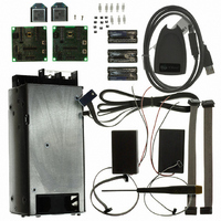
... Optional Add-Ons Rabbit has a Mesh Network Add-On Kit available for the RCM4510W. • Mesh Network Add-On Kit (Part No. 101-1272) ® Digi XBee USB (used as ZigBee coordinator) Two XBee ZB RF modules Two RF Interface modules ® serial cables Digi XBee USB and The XBee ZB RF module is installed on the RF Interface module, which can be con- nected via an RS-232 serial connection to a Windows PC for setup ...
Page 14
RabbitCore RCM4500W ...
Page 15
This chapter describes the RCM4510W hardware in more detail, and explains how to set up and use the accompanying Prototyping Board. NOTE: This chapter (and this manual) assume that you have the RCM4510W Develop- ment Kit. If you purchased an ...
Page 16
Hardware Connections There are three steps to connecting the Prototyping Board for use with Dynamic C and the sample programs: 1. Prepare the Prototyping Board for Development. 2. Attach the RCM4510W module to the Prototyping Board. 3. Connect the ...
Page 17
Step 2 — Attach Module to Prototyping Board Turn the RCM4510W module so that the mounting holes line up with the corresponding holes on the Prototyping Board with the programming header at the top right. Insert the metal standoffs ...
Page 18
Step 3 — Connect Programming Cable The programming cable connects the module to the PC running Dynamic C to download programs and to monitor the module during debugging. Connect the 10-pin connector of the programming cable labeled the RCM4510W ...
Page 19
Step 4 — Connect Power Once all the other connections have been made, you can connect power to the Prototyping Board. First, prepare the AC adapter for the country where it will be used by selecting the appro- priate ...
Page 20
Run a Sample Program If you already have Dynamic C installed, you are now ready to test your programming connections by running a sample program. Start Dynamic C by double-clicking on the Dynamic C icon on your desktop or ...
Page 21
Run a ZigBee Sample Program This section explains how to run a sample program in which the RCM4510W is used in its default setup as a router and the Digi ® 1. Connect the Digi XBee USB acting as ...
Page 22
Where From Here? If the sample program ran fine, you are now ready the sample programs in Chapter 3 and to develop your own applications. The sample programs fied for your own ...
Page 23
R To develop and debug programs for the RCM4510W (and for all other Rabbit hardware), you must install and use Dynamic C. This chapter provides a tour of its major features with respect to the RCM4510W. 3.1 Introduction To ...
Page 24
Sample Programs Of the many sample programs included with Dynamic C, several are specific to the RCM4510W modules. These programs will be found in the —Demonstrates use of the digital outputs by having you turn LEDs • CONTROLLED.C DS2 ...
Page 25
TAMPERDETECTION.C mode. When an attempt is detected, the battery-backed onchip-encryption RAM on the Rabbit 4000 is erased. This battery-backed onchip-encryption RAM can be useful to store data such as ...
Page 26
Serial Communication The following sample programs are found in the —This program demonstrates how to configure Serial Port D for • FLOWCONTROL.C CTS/RTS flow control with serial data coming from Serial Port C (TxC) at 115,200 bps. The serial ...
Page 27
RS-232 serial • SIMPLE3WIRE.C communication. Lower case characters are sent on TxC, and are received by RxD. The received characters are converted to upper case and are sent out on TxD, are received on RxC, and ...
Page 28
IOCONFIG_SWITCHECHO.C and F, which then transmit and then receive an ASCII string when switch pressed. The echoed serial data are displayed in the Dynamic C Note that the I/O lines that carry the Serial Port ...
Page 29
Real-Time Clock If you plan to use the real-time clock functionality in your application, you will need to set the real-time clock. Use the SETRTCKB.C folder, and follow the onscreen prompts. The SAMPLES\RTCLOCK program in the Dynamic C SAMPLES\RTCLOCK ...
Page 30
RabbitCore RCM4500W ...
Page 31
Chapter 4 describes the hardware components and principal hardware subsystems of the RCM4510W. Appendix A, “RCM4510W Specifica- tions,” provides complete physical and electrical specifications. Figure 6 shows the Rabbit-based subsystems designed into the RCM4510W. Figure 6. RCM4510W Subsystems User’s Manual ...
Page 32
RCM4510W Digital Inputs and Outputs Figure 7 shows the RCM4510W pinouts for headers J1 and J4. standard 2 × 25 IDC header with a nominal 1.27 mm pitch, and header J4 is Headers standard 2 ...
Page 33
Figure 8 shows the use of the Rabbit 4000 microprocessor ports in the RCM4510W modules. Figure 8. Use of Rabbit 4000 Ports The ports on the Rabbit 4000 microprocessor used in the RCM4510W are configurable, and so the factory defaults ...
Page 34
Table 2. RCM4510W Pinout Configurations Pin Pin Name 1 +3.3 V_IN 2 GND 3 /RES_OUT Reset output 4 /IORD Output 5 /IOWR Output 6 /RESET_IN Input 7 VBAT_EXT Battery input 8–15 PA[0:7] Input/Output 16 PB0 Input/Output 17 PB1 Input/Output 18 ...
Page 35
Table 2. RCM4510W Pinout Configurations (continued) Pin Pin Name 24 PC0 Input/Output 25 PC1 Input/Output 26 PC2 Input/Output 27 PC3 Input/Output 28 PC4 Input/Output 29 PC5 Input/Output 30 PC6 Input/Output 31 PC7 Input/Output 32 PE0 Input/Output User’s Manual Default Use ...
Page 36
Table 2. RCM4510W Pinout Configurations (continued) Pin Pin Name 33 PE1 Input/Output 34 PE2 Input/Output 35 PE3 Input/Output 36 PE4 Input/Output 37 PE5/SMODE0 Input/Output 38 PE6/SMODE1 Input/Output 39 PE7/STATUS Input/Output 30 Default Use Alternate Use I/O Strobe I1 A21 Timer ...
Page 37
Table 2. RCM4510W Pinout Configurations (continued) Pin Pin Name 40 PD0 Input/Output 41 PD1 Input/Output 42 PD2 Input/Output 43 PD3 Input/Output 44 PD4 Input/Output 45 PD5 Input/Output User’s Manual Default Use Alternate Use I/O Strobe I0 Timer C0 D8 INT0 ...
Page 38
Table 2. RCM4510W Pinout Configurations (continued) Pin Pin Name 46 PD6 Input/Output 47 PD7 Input/Output 48 CONVERT Analog Input Analog reference 49 VREF voltage 50 GND Ground 1 ADC0/DIO0 Input/Output 2 ADC1/DIO1 Input/Output 3 ADC2/DIO2 Input/Output 4 ADC3/DIO3 Input/Output 5 ...
Page 39
Memory I/O Interface The Rabbit 4000 address lines (A0–A19) and all the data lines (D0–D7) are routed inter- nally to the onboard flash memory and SRAM chips. I/0 write (/IOWR) and I/0 read (/IORD) are available for interfacing to ...
Page 40
Serial Communication The RCM4510W module does not have any serial driver or receiver chips directly on the board. However, a serial interface may be incorporated on the board the RCM4510W is mounted on. For example, the Prototyping Board has ...
Page 41
Table 3 summarizes the possible parallel port pins for the serial ports and their clocks. Table 3. Rabbit 4000 Serial Port and Clock Pins TXA PC6, PC7, PD6 Serial Port A RXA PC7, PD7, PE7 SCLKA PB1 TXB PC4, PC5, ...
Page 42
Programming Port The RCM4510W is programmed via the 10-pin header labeled J2. The programming port uses the Rabbit 4000’s Serial Port A for communication. Dynamic C uses the programming port to download and debug programs. Serial Port A is ...
Page 43
Programming Cable The programming cable is used to connect the programming port of the RCM4510W serial COM port. The programming cable converts the RS-232 voltage levels used by the PC serial port to the CMOS voltage ...
Page 44
A program “runs” in either mode, but can only be downloaded and debugged when the RCM4510W is in the Program Mode. Refer to the Rabbit 4000 Microprocessor User’s Manual gramming port. 4.3.2 Standalone Operation of the RCM4510W Once the RCM4510W ...
Page 45
Auxiliary I/O 4.4.1 Digital I/O The RCM4510W modules’ XBee RF module has up to five general-purpose I/O on header J4 — GPIO0, GPIO8, GPIO13, GPIO15, and GPIO16. Table 4 provides the names used in Dynamic C for these pins ...
Page 46
A/D Converter The RCM4510W modules’ XBee RF module has four inputs on header J4 that may be set up in software as analog inputs. The four analog input pins, ADC0–ADC3, each have an input impedance of 6–7 MΩ, depending ...
Page 47
If a device such as a battery is connected across two channels for a differential measurement, and it is not referenced to analog ground, then the current from the device will flow through both sets of attenuator resistors without flowing ...
Page 48
Other Hardware 4.5.1 Clock Doubler The clock doubler on the RCM4510W is disabled by default. 4.5.2 Spectrum Spreader The Rabbit 4000 features a spectrum spreader, which helps to mitigate EMI problems. The spectrum spreader default, but ...
Page 49
Memory 4.6.1 SRAM All RCM4510W modules have 512K of battery-backed data SRAM installed at U4. 4.6.2 Flash EPROM All RCM4510W modules also have 512K of flash EPROM installed at U3. NOTE: Rabbit recommends that any customer applications should not ...
Page 50
RabbitCore RCM4500W ...
Page 51
Dynamic integrated development system for writing embedded software. It runs on an IBM-compatible PC and is designed for use with single-board computers and other devices based on the Rabbit microprocessor. Chapter 5 describes the libraries and function ...
Page 52
Dynamic C has a number of standard features. • Full-feature source and/or assembly-level debugger, no in-circuit emulator required. • Royalty-free TCP/IP stack with source code and most common protocols. • Hundreds of functions in source-code libraries and sample programs: Exceptionally ...
Page 53
Dynamic C Function Calls 5.2.1 Digital I/O The RCM4510W was designed to interface with other systems, and so there are no drivers written specifically for the Rabbit 4000 I/O. The general Dynamic C read and write func- tions allow ...
Page 54
SRAM Use The RCM4510W module has a battery-backed data SRAM and a program-execution SRAM. Dynamic C provides the placed into the battery-backed SRAM. The compiler generates code that maintains two copies of each protected variable in the battery-backed SRAM. ...
Page 55
Including Firmware Update in Cloned Application If you include the firmware update in the master RCM4510W program, clone this program to an RCM4510W clone, and then let that program run on the clone, then the firmware update will fail ...
Page 56
Prototyping Board Function Calls The function calls described in this section are for use with the Prototyping Board features. The source code is in the Dynamic C library if you need to modify it for your own board design. ...
Page 57
Alerts These function calls can be found in the Dynamic C library. RCM4xxx.LIB void timedAlert(unsigned long timeout); DESCRIPTION Polls the real-time clock until a timeout occurs. The RCM4510W will low-power mode during this time. Once the ...
Page 58
Auxiliary I/O Pins Function Calls The function calls described in this section are for use with the pins on the auxiliary I/O header at J4. The source code is in the Dynamic C library if you need to modify ...
Page 59
The pins are configured as analog inputs or as digital I/O using the following macros as examples before #use XBEE_API.LIB. #define DIO_00 XBEE_IO_CONF_ANAIN #define DIO_01 XBEE_IO_CONF_ANAIN #define DIO_02 XBEE_IO_CONF_ANAIN #define DIO_03 XBEE_IO_CONF_ANAIN #define DIO_12 XBEE_IO_CONF_DIGIN #define DIO_05 XBEE_IO_CONF_DIGOUT_HIGH ...
Page 60
Digital I/O int zb_dio_in(int dio); DESCRIPTION Reads the logic state of a pin configured as a digital input pin. This value corresponds to the dio number. PARAMETERS the Dynamic C digital input pin number (0 – ZB_MAX_PIN, valid dio ...
Page 61
Analog Inputs int zb_adc_in(int dio); DESCRIPTION Reads the analog input on the designated pin and return its 10-bit value. To convert the reading to millivolts perform the following calculation. AD (mV) = (ADIO reading / 1023) × 1200 mV ...
Page 62
Upgrading Dynamic C Dynamic C patches that focus on bug fixes are available from time to time. Check the Web site www.rabbit.com/support/ 5.3.1 Add-On Modules Starting with Dynamic C version 10.40, Dynamic C includes the popular µC/OS-II real- time ...
Page 63
U 6.1 Introduction to the ZigBee Protocol The ZigBee PRO specification was ratified in April, 2007, and covers high-level communi- cation protocols for small, low-power digital modems based on the IEEE 802.15.4 stan- dard for wireless personal area networks ...
Page 64
ZNet vs. ZB Firmware RCM4510W modules are preconfigured with ZNet 2 router firmware. The firm- ware preloaded at the factory is indicated with the model number and is reflected in differ- ent part numbers (see Table 1). ...
Page 65
ZigBee Sample Programs In order to run the sample programs discussed in this chapter and elsewhere in this manual, 1. Your module must be plugged into the Prototyping Board as described in Chapter 2, “Getting Started.” 2. Dynamic C ...
Page 66
Now select the COM port the Digi Com Port” button. The message “Radio Found” is displayed to indicate that you selected the correct COM port. The ZigBee parameters (firmware version, operating channel, PAN ID) for the Digi box ...
Page 67
Setting up Sample Programs The sample programs are set up so that the RCM4510W module you are using is a ZigBee end device, router, or coordinator. Uncomment the line corresponding to the role the RCM4510W will have once it ...
Page 68
Node ID — the ID of your particular node via the macro in the Dynamic C Rabbit4000\XBee\XBEE_API.LIB identifier printable characters. • Defaults to RabbitXBee • Can be set to a global variable function ...
Page 69
The XBee sample programs in the Dynamic C the XBee function calls on the XBee RF module on the RCM4510W. —This sample program shows how to place the RCM4510W module in • SLEEPMODE.C the “sleep” mode where most power is ...
Page 70
RCM4510W module • SLEEPMODE2.C in the “sleep” mode where most power is removed from the RCM4510W module. Power is restored once a message is received or after a specified time interval. This ...
Page 71
Using the Sleep Mode The RCM4510W RabbitCore module has two components that are involved when the sleep mode is invoked — the XBee RF module and the Rabbit 4000 microprocessor. End devices, unlike coordinators and routers, can enter a ...
Page 72
Two additional parameters are described below for completeness. • WH determines how long the XBee RF module will hold a message for the RCM4510W to receive. Like ST, this parameter must be set carefully to ensure no mes- sages are ...
Page 73
Dynamic C Function Calls Function calls for use with the XBee RF modules are in the Dynamic C library. These ZigBee specific function calls are described in An XBee\XBEE_API.LIB Introduction to ZigBee, which is included in the online documentation ...
Page 74
RabbitCore RCM4500W ...
Page 75
Appendix A provides the specifications for the RCM4510W, and describes the conformal coating. User’s Manual A A. RCM4510W PPENDIX S PECIFICATIONS 69 ...
Page 76
A.1 Electrical and Mechanical Characteristics Figure A-1 shows the mechanical dimensions for the RCM4510W. Figure A-1. RCM4510W Dimensions NOTE: All measurements are in inches followed by millimeters enclosed in parentheses. All dimensions have a manufacturing tolerance of ±0.01" (0.25 mm). ...
Page 77
It is recommended that you allow for an “exclusion zone” of 0.04" (1 mm) around the RCM4510W in all directions when the RCM4510W is incorporated into an assembly that includes other printed circuit boards. An “exclusion zone” of 0.08" (2 ...
Page 78
Table A-1 lists the electrical, mechanical, and environmental specifications for the RCM4510W. Table A-1. RCM4510W Specifications Parameter Microprocessor Flash Memory Data SRAM Backup Battery General Purpose I/O Additional Inputs Additional Outputs * Analog Inputs • A/D Converter Resolution • A/D ...
Page 79
Table A-1. RCM4510W Specifications (continued) Parameter Pulse-Width Modulators Input Capture Quadrature Decoder ® Power with ZigBee Modem (pins unloaded) Operating Temperature Humidity Connectors Board Size with XBee RF module Installed RF Module Compliance * These I/O pins from the XBee ...
Page 80
A.1.1 XBee RF Module Table A-2 shows the XBee RF module specifications. Table A-2. XBee RF Module Specifications Parameter RF Module Compliance Frequency Indoor Range Outdoor Line-of-Sight Range Performance Transmit Power Output RF Data Rate Receiver Sensitivity Antenna Supported Network ...
Page 81
A.1.2 Headers The RCM4510W uses a header at J1 for physical connection to other boards × 25 SMT header with a 1.27 mm pin spacing. J2, the programming port × 5 header with ...
Page 82
A.2 Rabbit 4000 DC Characteristics Table A-3. Rabbit 4000 Absolute Maximum Ratings Symbol T Operating Temperature A T Storage Temperature S V Maximum Input Voltage IH VDD Maximum Operating Voltage IO Stresses beyond those listed in Table A-3 may cause ...
Page 83
A.3 I/O Buffer Sourcing and Sinking Limit Unless otherwise specified, the Rabbit I/O buffers are capable of sourcing and sinking current per pin at full AC switching speed. Full AC switching assumes a 29.4 MHz CPU clock ...
Page 84
Figure A-4 shows a typical timing diagram for the Rabbit 4000 microprocessor external I/O read and write cycles. Figure A-4. External I/O Read and Write Cycles—No Extra Wait States NOTE: /IOCSx can be programmed to be active low (default) or ...
Page 85
Table A-7 lists the delays in gross memory access time for several values of VDD Table A-7. Preliminary Data and Clock Delays Clock to Address Output Delay VDD (ns ...
Page 86
A.5 Conformal Coating The areas around the 32 kHz real-time clock crystal oscillator have had the Dow Corning silicone-based 1-2620 conformal coating applied. The conformally coated area is shown in Figure A-5. The conformal coating protects these high-impedance circuits from ...
Page 87
A.6 Jumper Configurations Figure A-6 shows the header locations used to configure the various RCM4510W options via jumpers. Figure A-6. Location of RCM4510W Configurable Positions Table A-8 lists the configuration options. Table A-8. RCM4510W Jumper Configurations Header Description PE5 or ...
Page 88
Table A-8. RCM4510W Jumper Configurations (continued) Header Description JP5 LN2 or PD2 on J1 pin 42 JP6 LN4 or PD4 on J1 pin 44 JP7 LN6 or PD6 on J1 pin 46 JP8 LN7 or PD7 on J1 pin 47 ...
Page 89
A PPENDIX Appendix B describes the features and accessories of the Proto- typing Board, and explains the use of the Prototyping Board to demonstrate the RCM4510W and to build prototypes of your own circuits. The Prototyping Board has power-supply connec- ...
Page 90
B.1 Introduction The Prototyping Board included in the Development Kit makes it easy to connect an RCM4510W module to a power supply and a PC workstation for development. It also pro- vides some basic I/O peripherals (RS-232, LEDs, and switches), ...
Page 91
B.1.1 Prototyping Board Features —A a 3-pin header is provided for connection to the power supply. Power Connection • Note that the 3-pin header is symmetrical, with both outer pins connected to ground and the center pin connected to the ...
Page 92
RabbitCore module are pre- Analog Inputs Header • sented at header J3 on the Prototyping Board. These analog signals are connected via attenuator/filter circuits on the Prototyping Board to the corresponding analog inputs on the ...
Page 93
B.2 Mechanical Dimensions and Layout Figure B-2 shows the mechanical dimensions and layout for the Prototyping Board. Figure B-2. Prototyping Board Dimensions NOTE: All measurements are in inches followed by millimeters enclosed in parentheses. All dimensions have a manufacturing tolerance ...
Page 94
Table B-1 lists the electrical, mechanical, and environmental specifications for the Proto- typing Board. Table B-1. Prototyping Board Specifications Parameter Board Size Operating Temperature Humidity Input Voltage Maximum Current Draw (including user-added circuits) Prototyping Area Connectors B.3 Power Supply The ...
Page 95
B.4 Using the Prototyping Board The Prototyping Board is actually both a demonstration board and a prototyping board demonstration board, it can be used to demonstrate the functionality of the RCM4510W right out of the box without any ...
Page 96
All signals from the RCM4510W module are available on header J2 of the Prototyping Board. The remaining ports on the Rabbit 4000 microprocessor are used for RS-232 serial communication. Table B-2 lists the signals on header J2 and, where applicable, ...
Page 97
B.4.1 Adding Other Components There are pads for 28-pin TSSOP devices, 16-pin SOIC devices, and 6-pin SOT devices that can be used for surface-mount prototyping with these devices. There are also pads that can be used for SMT resistors and ...
Page 98
B.4.3 Analog Features The Prototyping Board has typical support circuitry installed to complement the ADS7870 A/D converter chip, which is available on other RabbitCore modules based on the Rabbit 4000 microprocessor, but is not installed on the RCM4510W model. the ...
Page 99
RS-232 flow control on an RS-232 port is initiated in software using the function call from trolOn RS232.LIB of the flow control lines are specified using a set of five macros. SERX_RTS_PORT—Data register for the parallel port that the RTS ...
Page 100
B.5 Prototyping Board Jumper Configurations Figure B-6 shows the header locations used to configure the various Prototyping Board options via jumpers. Figure B-6. Location of Configurable Jumpers on Prototyping Board Table B-4 lists the configuration options using either jumpers or ...
Page 101
Table B-4. RCM4510W Prototyping Board Jumper Configurations (continued) Header Description JP5 PC1/RxD/Switch S2 JP6 JP7 PC2/TxC/LED DS3 JP8 JP9 PC3/RxC/Switch S3 JP10 LN0 buffer/filter to JP11 RCM4510W JP12 PB2/LED DS2 LN1 buffer/filter to JP13 RCM4510W JP14 PB3/LED DS3 LN2 buffer/filter ...
Page 102
Table B-4. RCM4510W Prototyping Board Jumper Configurations (continued) Header Description LN5 buffer/filter to JP20 RCM4510W LN6 buffer/filter to JP21 RCM4510W LN7 buffer/filter to JP22 RCM4510W JP23 LN4_IN–LN6_IN JP24 LN0_IN–LN3_IN JP25 Thermistor Location NOTE: Jumper connections JP3–JP10, JP12, JP14, JP16, JP18, ...
Page 103
A Appendix C provides information on the current requirements of the RCM4510W, and includes some background on the chip select circuit used in power management. C.1 Power Supplies The RCM4510W requires a regulated 3 ±5% power source. The ...
Page 104
The drain on the battery by the RCM4510W is typically 7.5 µA when no other power is supplied 165 mA·h battery is used, the battery can last about 2.5 years: 165 mA·h ----------------------- - = 2.5 years. 7.5 ...
Page 105
V and 3.00 V, typically 2.93 V. Since the RCM4510W will operate at voltages as low as 3.0 V, exercise care when operating close to the 3.0 V minimum voltage (for example, keep the power supply as close as ...
Page 106
RabbitCore RCM4500W ...
Page 107
... A Dynamic C library of the type RCM4510W. User’s Manual PPENDIX I NSTRUCTIONS ® XBee USB used as sample program does not inadvertently reload (or is used for a coordinator XB24-ZB_21….LIB is used for a router RCM4510W. XB24-ZB_23….LIB is used for an end-device XB24-ZB_29….LIB DDITIONAL folder. 101 ...
Page 108
There are also two ZNet 2.5 libraries in the folder. ZNet • A Dynamic C library of the type RCM4510W. • A Dynamic C library of the type device/router RCM4510W. Make the following modifications to the run it according to ...
Page 109
D.1.3 Dynamic C v. 10.11 (RCM4510W preview version only) The coordinator and end-device/router firmware is provided in the Dynamic C folder. RCM4500W\MODEMFW • Firmware of the type XB24-B_ZigBee_11….ebl RCM4510W. • Firmware of the type XB24-B_ZigBee_13….ebl RCM4510W. When you use the ...
Page 110
D.2 Digi XBee USB Configuration You may experience difficulty when you use the ZigBee sample programs and the Digi XBee USB with the default settings if you are working simultaneously with more than one ZigBee coordinator. Section 6.2.2 explains ...
Page 111
On the “PC Settings” tab, select the “USB Serial Port” corresponding to the USB serial port the Digi ® XBee USB is connected to and click “Test/Query.” You should see a response showing the Modem Type (XB 24-B) and ...
Page 112
D.2.1 Additional Reference Information Check Digi’s Web site for the latest information and documentation on the XBee RF module, the X-CTU utility, and the Digi ® PRO RF modules are presently not compatible with the XBeeRF module used with the ...
Page 113
... Digi® XBee USB ........... 106 firmware updates ......... 106 via cloned application ....... 49 XBee RF module ............ 101 coordinator vs. end device/ router ................ 102, 103 firmware updates . 101, 106 flash memory addresses user blocks ........................ 43 H hardware connections install RCM4510W on Proto- typing Board ................. 11 power supply ..................... 13 programming cable ...
Page 114
... FLOWCONTROL.C .....20 IOCONFIG_ SWITCHECHO.C ......22 PARITY.C .....................20 SERDMA.C ...................20 SIMPLE3WIRE.C .........21 SIMPLE5WIRE.C .........21 SWITCHCHAR.C .........21 sleep mode .........................66 USERBLOCK_CLEAR.C 47 USERBLOCK_INFO.C ....47 XBee RF module AT_INTERACTIVE.C ...............15, 62, 101, 105 AT_RUNONCE.C .........62 MODEMFWLOAD.C ...........................101, 102 SLEEPMODE.C ............63 SLEEPMODE2.C ..........64 XBEE_GPIO_SERVER.C ...............................59, 64 ZigBee setup ......................59 serial communication ............34 function calls .....................47 Prototyping Board RS-232 ...........................92 software PACKET.LIB ................47 RS232 ...
Page 115
... X XBee firmware ....................... 6 upgrading to ZB ................ 58 ZB ................................. 6, 58 Znet 2.5 ......................... 6, 58 Znet 2.5 vs. ZB ................. 58 XBee RF module additional resources .......... 67 firmware download ......... 101 function calls xb_sleep() ...................... 99 zb_Rabbit_poweroff() ... 99 Z ZigBee software libraries .............. 49 ZigBee protocol coordinator ........................ 57 end device ......................... 57 introduction ....................... 57 mesh network .................... 57 router ...
Page 116
RabbitCore RCM4500W ...
Page 117
RCM4500W Schematic (preview version) www.rabbit.com/documentation/schemat/090-0242.pdf 090-0246 RCM4500W Schematic (standard release) www.rabbit.com/documentation/schemat/090-0246.pdf 090-0230 Prototyping Board Schematic www.rabbit.com/documentation/schemat/090-0230.pdf 090-0128 Programming Cable Schematic www.rabbit.com/documentation/schemat/090-0128.pdf 090-0252 USB Programming Cable Schematic www.rabbit.com/documentation/schemat/090-0252.pdf You may use the URL information provided above to access the latest ...
Page 118
...