101-1279 Rabbit Semiconductor, 101-1279 Datasheet - Page 130
101-1279
Manufacturer Part Number
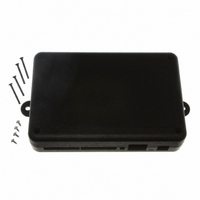
101-1279
Description
PLASTIC ENCLOSURE FOR BL4S100
Manufacturer
Rabbit Semiconductor
Datasheet
1.20-101-1258.pdf
(144 pages)
Specifications of 101-1279
Accessory Type
Enclosure
Product
Prototyping Accessories
Processor Type
BL4S100
Board Size
146 mm x 96 mm x 16 mm
Interface Type
Ethernet
For Use With/related Products
BL4S100
Lead Free Status / RoHS Status
Not applicable / Not applicable
Other names
316-1159


D.2 Interpreting Error Codes
Some BL4S100 function calls may return a Mode Conflict error code. This error code is a
4-bit value that identifies other pins using the same counter/timer block on a RIO chip that
require this block to be in a mode that conflicts with the functionality that has already been
requested — the additional functionality requested cannot be supported. The error code also
helps you identify the other pins whose functionality needs to change to possibly allow the
latest function call to succeed.
The bit values in the Mode Conflict error codes have the following meanings.
• Bits [7:4] don’t matter, will always be zero
• Bit 3 — Pin 3 of this block has a mode conflict
• Bit 2 — Pin 2 of this block has a mode conflict
• Bit 1 — Pin 1 of this block has a mode conflict
• Bit 0 — Pin 0 of this block has a mode conflict
By looking at the table in this appendix, you can identify the other pins that share the RIO
counter/timer block with the pin(s) that returned the Mode Conflict error code. For example,
if you already configured IN0 and IN1 as Quadrature Decoder inputs, then try to set IN2
as a counter input, the function call will return a Mode Conflict error code of 3.
This error code is a 4-bit value that identifies other pins using the same counter/timer
block that conflict with the requested function. In this case, 3 is 0011, which indicates that
pin 1 and pin 2 of the block used by IN2 have the conflicts — they are using the coun-
ter/timer in a way that conflicts with setting IN2 as a counter input. Looking at Table D-1,
you find IN2 is using block 0 on RIO chip 0, and pin 0 and pin 1 of this block are used by
IN0 and IN1. Therefore you cannot use IN2 as a counter input unless you remove the
Quadrature Decoder inputs from this block. This illustrates how the Mode Conflict error
code can be used to identify the pin functions that cannot mix together on the same RIO
block.
The tables in this appendix are useful for both finding the cause of mode conflicts, and for
planning which pins to use for which functions to avoid conflicts in the first place.
Notice that there is a pattern to the block sharing of certain I/O pins. The first six digital
input pins, IN0—IN5, have blocks shared across four inputs. These are the only pins that
can support functions such as Quadrature Decoder inputs with an independent index-
based reset. The next group of eight digital I/O pins (IN6–IN9 and OUT0–OUT3) share
blocks among their digital I/O pairs, bringing both the input and output functionality of
these pins into the same block. This allows PWM or PPM outputs that can be used with an
external synchronization signal. It would also allow synchronization of a pulse capture
response to a PWM-based output pulse. The last remaining I/O pins have nonshared RIO
blocks available for both the input and output functionality, making these pins ideal for
single-pin functions requiring a counter/timer.
BL4S100 User’s Manual
128
Related parts for 101-1279
Image
Part Number
Description
Manufacturer
Datasheet
Request
R

Part Number:
Description:
COMPUTER SNGLBD BL2120 FRCTNLOCK
Manufacturer:
Rabbit Semiconductor
Datasheet:

Part Number:
Description:
KIT APPLCTN RABBITCORE RCM4010
Manufacturer:
Rabbit Semiconductor
Datasheet:

Part Number:
Description:
KIT MESH NETWORK ADD-ON RCM4510W
Manufacturer:
Rabbit Semiconductor
Datasheet:

Part Number:
Description:
KIT DEV FOR BL2500 COYOTE
Manufacturer:
Rabbit Semiconductor
Datasheet:

Part Number:
Description:
KIT APPLICATION SIMPLE SENSOR
Manufacturer:
Rabbit Semiconductor
Datasheet:


Part Number:
Description:
PWR SUPPLY UNIV 110/240VAC-12VDC
Manufacturer:
Rabbit Semiconductor

Part Number:
Description:
IC CPU RABBIT2000 30MHZ 100PQFP
Manufacturer:
Rabbit Semiconductor
Datasheet:

Part Number:
Description:
IC CPU RABBIT4000 128-LQFP
Manufacturer:
Rabbit Semiconductor
Datasheet:
Part Number:
Description:
IC MPU RABIT3000A 55.5MHZ128LQFP
Manufacturer:
Rabbit Semiconductor
Datasheet:

Part Number:
Description:
MODULE RABBITCORE RCM4010
Manufacturer:
Rabbit Semiconductor
Datasheet:

Part Number:
Description:
RCM4110 RABBITCORE
Manufacturer:
Rabbit Semiconductor
Datasheet:

Part Number:
Description:
MODULE RABBITCORE RCM2000
Manufacturer:
Rabbit Semiconductor
Datasheet:

Part Number:
Description:
MODULE RABBITCORE RCM3000
Manufacturer:
Rabbit Semiconductor
Datasheet:

Part Number:
Description:
MCU RCM4000 RABBITCORE
Manufacturer:
Rabbit Semiconductor
Datasheet: