101-1279 Rabbit Semiconductor, 101-1279 Datasheet - Page 41
101-1279
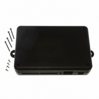
Manufacturer Part Number
101-1279
Description
PLASTIC ENCLOSURE FOR BL4S100
Manufacturer
Rabbit Semiconductor
Datasheet
1.20-101-1258.pdf
(144 pages)
Specifications of 101-1279
Accessory Type
Enclosure
Product
Prototyping Accessories
Processor Type
BL4S100
Board Size
146 mm x 96 mm x 16 mm
Interface Type
Ethernet
For Use With/related Products
BL4S100
Lead Free Status / RoHS Status
Not applicable / Not applicable
Other names
316-1159


•
•
•
BL4S100 User’s Manual
INTERRUPTS.C
Set up the Demonstration Board as shown in Figure 14 with IN0 connected to SW1.
The sample program sets up two interrupt sources, an external interrupt tied to pushbutton
switch SW1, and a rollover interrupt tied to a timer that is producing a PWM output.
The Dynamic C
the PWM signal was started. The window will also display Button Pressed each time
the pushbutton switch is pressed. Each time the button is pressed, the timeout timer that
removes the message is reset, so you can keep the message on the screen indefinitely by
pressing the button repeatedly.
PPM.C
on headers J3 and J4. The PPM signals are set for a frequency of 200 Hz, with the duty
cycle adjustable from 0 to 100% and an offset adjustable from 0 to 100% by the user.
These pins can be connected to an oscilloscope to view the waveform being generated.
The overall frequency can be adjusted in the
instructions when running this sample program.
Once you compile and run the sample program, change the duty cycle and offsets for a
given PPM channel via the Dynamic C
forms on the oscilloscope. Signals on OUT0 and OUT1 will all be synchronized with
each other as they share the same overall counter block that sets the cycle frequency.
The same is true for PPM signals on OUT2 and OUT3 (and the remaining digital outputs
when you connect them to J1 on the Demonstration Board instead of those already
connected). The two blocks may have a phase shift from each other, but will run at the
same frequency.
PULSE_CAPTURE.C
channels on the digital I/O pins on header J3. The input capture feature allows the begin
and end positions of a pulse to be measured in a given time window. We take advantage
of the counter synchronization feature of the underlying Rabbit RIO chip to create cap-
ture windows and pulse modulation windows that are synchronized. This guarantees
that we always catch the begin edge first on a quickly repeating waveform. This was
done to create an interactive element to this sample program, but capturing real-world
repetitive signals will usually not have this advantage. Refer to Appendix D for more
information on how to use the input capture.feature. Follow the instructions below
when running this sample program.
1. The digital outputs on the BL4S100 do not have an internal pull-up resistor and will not register on
2. Connect the oscilloscope probe to digital output pins OUT0–OUT3 on headers J3 or J4. Remember
1. Connect I/O pins IN0 and OUT0 together.
2. Connect I/O pins IN3 and OUT2 together.
3. Connect the oscilloscope ground to GND on header J3.
4. Use the oscilloscope probes on the IN0 and the OUT0 pair or the
the oscilloscope without a pull-up resistor. The Demonstration Board has pull-up resistors—
connect OUT0–OUT3 on the BL4S100 to SW1–SW4 on header J1 of the Demonstration Board.
to connect the oscilloscope ground to GND on header J4.
IN3 and OUT2 pair to view the PPM signals.
—Demonstrates the use of up to eight PPM channels on the digital output pins
STDIO
—Demonstrates the use of the Rabbit RIO interrupt service capabilities.
—Demonstrates the use of two input capture inputs tied to PPM
window will show a count of rollovers that have occurred since
STDIO
#define PPM_FREQ
window and watch the change in wave-
line. Follow these
39
Related parts for 101-1279
Image
Part Number
Description
Manufacturer
Datasheet
Request
R

Part Number:
Description:
COMPUTER SNGLBD BL2120 FRCTNLOCK
Manufacturer:
Rabbit Semiconductor
Datasheet:

Part Number:
Description:
KIT APPLCTN RABBITCORE RCM4010
Manufacturer:
Rabbit Semiconductor
Datasheet:

Part Number:
Description:
KIT MESH NETWORK ADD-ON RCM4510W
Manufacturer:
Rabbit Semiconductor
Datasheet:

Part Number:
Description:
KIT DEV FOR BL2500 COYOTE
Manufacturer:
Rabbit Semiconductor
Datasheet:

Part Number:
Description:
KIT APPLICATION SIMPLE SENSOR
Manufacturer:
Rabbit Semiconductor
Datasheet:


Part Number:
Description:
PWR SUPPLY UNIV 110/240VAC-12VDC
Manufacturer:
Rabbit Semiconductor

Part Number:
Description:
IC CPU RABBIT2000 30MHZ 100PQFP
Manufacturer:
Rabbit Semiconductor
Datasheet:

Part Number:
Description:
IC CPU RABBIT4000 128-LQFP
Manufacturer:
Rabbit Semiconductor
Datasheet:
Part Number:
Description:
IC MPU RABIT3000A 55.5MHZ128LQFP
Manufacturer:
Rabbit Semiconductor
Datasheet:

Part Number:
Description:
MODULE RABBITCORE RCM4010
Manufacturer:
Rabbit Semiconductor
Datasheet:

Part Number:
Description:
RCM4110 RABBITCORE
Manufacturer:
Rabbit Semiconductor
Datasheet:

Part Number:
Description:
MODULE RABBITCORE RCM2000
Manufacturer:
Rabbit Semiconductor
Datasheet:

Part Number:
Description:
MODULE RABBITCORE RCM3000
Manufacturer:
Rabbit Semiconductor
Datasheet:

Part Number:
Description:
MCU RCM4000 RABBITCORE
Manufacturer:
Rabbit Semiconductor
Datasheet: