IAR-KSK-IMX25 Freescale Semiconductor, IAR-KSK-IMX25 Datasheet - Page 16
IAR-KSK-IMX25
Manufacturer Part Number
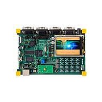
IAR-KSK-IMX25
Description
KIT DEVELOPMENT I.MX257, ARM926
Manufacturer
Freescale Semiconductor
Series
i.MX25r
Type
MCUr
Datasheets
1.MCIMX25WPDKJ.pdf
(2 pages)
2.IAR-KSK-IMX25.pdf
(154 pages)
3.IAR-KSK-IMX25.pdf
(2 pages)
4.IAR-KSK-IMX25.pdf
(57 pages)
Specifications of IAR-KSK-IMX25
Contents
Board, Cables, CD, Debugger, Power Supply
Processor To Be Evaluated
I.MX257
Processor Series
i.MX25
Data Bus Width
16 bit
Interface Type
UART, JTAG, USB, Ethernet, SD/MMC
Core
ARM926EJ-S
Silicon Manufacturer
Freescale
Core Architecture
ARM
Core Sub-architecture
ARM9
Silicon Core Number
I.MX2
Silicon Family Name
I.MX25
Mcu Supported Families
I.MX25
For Use With/related Products
i.MX25
Lead Free Status / RoHS Status
Lead free / RoHS Compliant


3.2
Any i.MX25 board design must comply with the power-up and power-down sequence guidelines given in
this section to ensure reliable operation of the device. Recommended power-up and power-down
sequences are given in the following subsections.
3.2.1
The following power-up sequence is recommended:
16
1. Assert power on reset (POR).
2. Turn on digital logic domain and I/O power supplies VDDn and NVCCx.
3. Turn on all other analog power supplies, including USBPHY1_VDDA_BIAS,
4. Negate the POR signal.
USBPHY1_UPLL_VDD, USBPHY1_VDDA, USBPHY2_VDD, OSC24M_VDD,
MPPLL_VDD, UPLL_VDD, NVCC_ADC, and FUSEVDD (FUSEVDD is tied to GND if fuses
are not being programmed). The minimum time between turning on each power supply is the time
it takes for the previous supply to be stable.
Supply Power-Up/Power-Down Requirements and Restrictions
Power-Up Sequence
Deviations from the guidelines in this section may result in the following
situations:
•
•
•
For security applications, the coin battery must be connected during both
power-up and power-down sequences to ensure that security keys are not
unintentionally erased.
•
•
•
i.MX25 Applications Processor for Consumer and Industrial Products, Rev. 8
Excessive current during power-up phase
Prevention of the device from booting
Irreversible damage to the i.MX25 (worst-case scenario)
The user is advised to connect FUSEVDD to GND except when fuses
are being programmed, in order to prevent unintentional blowing of
fuses.
Other power-up sequences may be possible; however, the above
sequence has been verified and is recommended.
There is a 1-ms minimum time between supplies coming up, and a 1-ms
minimum time between POR_B assert and deassert.
CAUTION
NOTE
NOTE
Freescale Semiconductor
Related parts for IAR-KSK-IMX25
Image
Part Number
Description
Manufacturer
Datasheet
Request
R

Part Number:
Description:
Manufacturer:
Freescale Semiconductor, Inc
Datasheet:
Part Number:
Description:
Manufacturer:
Freescale Semiconductor, Inc
Datasheet:
Part Number:
Description:
Manufacturer:
Freescale Semiconductor, Inc
Datasheet:
Part Number:
Description:
Manufacturer:
Freescale Semiconductor, Inc
Datasheet:
Part Number:
Description:
Manufacturer:
Freescale Semiconductor, Inc
Datasheet:
Part Number:
Description:
Manufacturer:
Freescale Semiconductor, Inc
Datasheet:
Part Number:
Description:
Manufacturer:
Freescale Semiconductor, Inc
Datasheet:
Part Number:
Description:
Manufacturer:
Freescale Semiconductor, Inc
Datasheet:
Part Number:
Description:
Manufacturer:
Freescale Semiconductor, Inc
Datasheet:
Part Number:
Description:
Manufacturer:
Freescale Semiconductor, Inc
Datasheet:
Part Number:
Description:
Manufacturer:
Freescale Semiconductor, Inc
Datasheet:
Part Number:
Description:
Manufacturer:
Freescale Semiconductor, Inc
Datasheet:
Part Number:
Description:
Manufacturer:
Freescale Semiconductor, Inc
Datasheet:
Part Number:
Description:
Manufacturer:
Freescale Semiconductor, Inc
Datasheet:
Part Number:
Description:
Manufacturer:
Freescale Semiconductor, Inc
Datasheet: