IAR-KSK-IMX25 Freescale Semiconductor, IAR-KSK-IMX25 Datasheet - Page 124
IAR-KSK-IMX25
Manufacturer Part Number
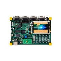
IAR-KSK-IMX25
Description
KIT DEVELOPMENT I.MX257, ARM926
Manufacturer
Freescale Semiconductor
Series
i.MX25r
Type
MCUr
Datasheets
1.MCIMX25WPDKJ.pdf
(2 pages)
2.IAR-KSK-IMX25.pdf
(154 pages)
3.IAR-KSK-IMX25.pdf
(2 pages)
4.IAR-KSK-IMX25.pdf
(57 pages)
Specifications of IAR-KSK-IMX25
Contents
Board, Cables, CD, Debugger, Power Supply
Processor To Be Evaluated
I.MX257
Processor Series
i.MX25
Data Bus Width
16 bit
Interface Type
UART, JTAG, USB, Ethernet, SD/MMC
Core
ARM926EJ-S
Silicon Manufacturer
Freescale
Core Architecture
ARM
Core Sub-architecture
ARM9
Silicon Core Number
I.MX2
Silicon Family Name
I.MX25
Mcu Supported Families
I.MX25
For Use With/related Products
i.MX25
Lead Free Status / RoHS Status
Lead free / RoHS Compliant


3.7.20.2
Table 98
Figure 97
parameters (USB15–USB17) shown in the figure.
4
4.1
Figure 98
124
US15
US16
US17
USB_Data[7:0]
USB_Clk
USB_Stp
USB_Nxt
USB_Dir
•
•
ID
Name
Package Information and Contact Assignment
All dimensions in millimeters.
Dimensioning and tolerancing per ASME Y14.5M-1994.
defines the USB parallel interface signals.
400 MAPBGA—Case 17x17 mm, 0.8 mm Pitch
shows the USB parallel mode transmit/receive waveform.
USB_Dir/Nxt
shows the 17×17 mm i.MX25 production package. The following notes apply to
USB_Data
USB_Clk
USB_Stp
Setup time (Dir&Nxt in, Data in)
Hold time (Dir&Nxt in, Data in)
Output delay time (Stp out, Data out
USB Parallel Interface Timing
Direction
Out
I/O
In
In
In
i.MX25 Applications Processor for Consumer and Industrial Products, Rev. 8
Figure 97. USB Parallel Mode Transmit/Receive Waveform
Interface clock—All interface signals are synchronous to USB_Clk
Bidirectional data bus, driven low by the link during idle—Bus ownership is determined by the
direction
Direction—Control the direction of the data bus
Stop—The link asserts this signal for one clock cycle to stop the data stream currently on the bus
Next—The PHY asserts this signal to throttle the data
US15
Table 98. Signal Definitions for USB Parallel Interface
Table 99. USB Timing Specification in Parallel Mode
US15
Parameter
US16
US16
US17
Signal Description
Min.
—
—
—
Table 99
Max.
6.0
0.0
9.0
US17
describes the timing
Unit
ns
ns
ns
Freescale Semiconductor
Reference Signal
Conditions/
Figure
10 pF
10 pF
10 pF
98:
Related parts for IAR-KSK-IMX25
Image
Part Number
Description
Manufacturer
Datasheet
Request
R

Part Number:
Description:
Manufacturer:
Freescale Semiconductor, Inc
Datasheet:
Part Number:
Description:
Manufacturer:
Freescale Semiconductor, Inc
Datasheet:
Part Number:
Description:
Manufacturer:
Freescale Semiconductor, Inc
Datasheet:
Part Number:
Description:
Manufacturer:
Freescale Semiconductor, Inc
Datasheet:
Part Number:
Description:
Manufacturer:
Freescale Semiconductor, Inc
Datasheet:
Part Number:
Description:
Manufacturer:
Freescale Semiconductor, Inc
Datasheet:
Part Number:
Description:
Manufacturer:
Freescale Semiconductor, Inc
Datasheet:
Part Number:
Description:
Manufacturer:
Freescale Semiconductor, Inc
Datasheet:
Part Number:
Description:
Manufacturer:
Freescale Semiconductor, Inc
Datasheet:
Part Number:
Description:
Manufacturer:
Freescale Semiconductor, Inc
Datasheet:
Part Number:
Description:
Manufacturer:
Freescale Semiconductor, Inc
Datasheet:
Part Number:
Description:
Manufacturer:
Freescale Semiconductor, Inc
Datasheet:
Part Number:
Description:
Manufacturer:
Freescale Semiconductor, Inc
Datasheet:
Part Number:
Description:
Manufacturer:
Freescale Semiconductor, Inc
Datasheet:
Part Number:
Description:
Manufacturer:
Freescale Semiconductor, Inc
Datasheet: