IAR-KSK-IMX25 Freescale Semiconductor, IAR-KSK-IMX25 Datasheet - Page 117
IAR-KSK-IMX25
Manufacturer Part Number
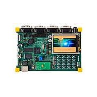
IAR-KSK-IMX25
Description
KIT DEVELOPMENT I.MX257, ARM926
Manufacturer
Freescale Semiconductor
Series
i.MX25r
Type
MCUr
Datasheets
1.MCIMX25WPDKJ.pdf
(2 pages)
2.IAR-KSK-IMX25.pdf
(154 pages)
3.IAR-KSK-IMX25.pdf
(2 pages)
4.IAR-KSK-IMX25.pdf
(57 pages)
Specifications of IAR-KSK-IMX25
Contents
Board, Cables, CD, Debugger, Power Supply
Processor To Be Evaluated
I.MX257
Processor Series
i.MX25
Data Bus Width
16 bit
Interface Type
UART, JTAG, USB, Ethernet, SD/MMC
Core
ARM926EJ-S
Silicon Manufacturer
Freescale
Core Architecture
ARM
Core Sub-architecture
ARM9
Silicon Core Number
I.MX2
Silicon Family Name
I.MX25
Mcu Supported Families
I.MX25
For Use With/related Products
i.MX25
Lead Free Status / RoHS Status
Lead free / RoHS Compliant


1
2
3.7.19.2.4
Figure 88
Table 89
1
2
3.7.20
This section describes timing for the USB OTG port and host ports. Both serial and parallel interfaces are
described.
3.7.20.1
The USB serial transceiver is configurable to four modes supporting four different serial interfaces:
The following subsections describe the timings for these four modes.
Freescale Semiconductor
UA5
UA6
UA3
UA4
F
T
ID
Note: The UART receiver can tolerate 1/(16 × F
not exceed 3/(16 × F
F
ID
ref_clk
baud_rate
(input)
baud_rate
•
•
•
•
RXD
Receive bit time
: The period of UART reference clock ref_clk ( ipg_perclk after RFDIV divider).
DAT_SE0 bidirectional, 3-wire mode
DAT_SE0 unidirectional, 6-wire mode
VP_VM bidirectional, 4-wire mode
VP_VM unidirectional, 6-wire mode
Transmit bit time in IrDA mode
describes the timing parameters (UA5–UA6) shown in the figure.
Receive IR pulse duration
: Baud rate frequency. The maximum baud rate the UART can support is ( ipg_perclk frequency)/16.
: Baud rate frequency. The maximum baud rate the UART can support is ( ipg_perclk frequency)/16.
shows the UART receive timing for IrDA mode, for a format of 8 data bits and 1 stop bit.
Transmit IR pulse duration
USBOTG Timing
USB Serial Interface Timing
Start
Bit
UART IrDA Mode Receive Timing
Parameter
Parameter
UA5
i.MX25 Applications Processor for Consumer and Industrial Products, Rev. 8
baud_rate
1
in IrDA mode
Bit 0
Table 88. UART IrDA Mode Transmit Timing Parameters
Table 89. UART IrDA Mode Receive Timing Parameters
).
Figure 88. UART IrDA Mode Receive Timing Diagram
Bit 1
Symbol
t
RIRpulse
t
RIRbit
Symbol
t
TIRpulse
t
TIRbit
Bit 2
baud_rate
1/F
UA5
baud_rate
(3/16) × (1/F
) tolerance in each bit. But accumulation tolerance in one frame must
1/F
Bit 3
baud_rate
2
1.41 us
– 1/(16 × F
Min.
baud_rate
Min.
Bit 4
1
– T
ref_clk
) – T
baud_rate
UA6
Bit 5
ref_clk
2
)
1/F
(3/16) × (1/F
Bit 6
baud_rate
1/F
(5/16) × (1/F
baud_rate
+ 1/(16 × F
Bit 7
baud_rate
Max.
Max.
UA5
+ T
baud_rate
ref_clk
) + T
Possible
Parity
baud_rate
Bit
ref_clk
)
UA5
)
STOP
Units
BIT
Units
—
—
—
—
117
Related parts for IAR-KSK-IMX25
Image
Part Number
Description
Manufacturer
Datasheet
Request
R

Part Number:
Description:
Manufacturer:
Freescale Semiconductor, Inc
Datasheet:
Part Number:
Description:
Manufacturer:
Freescale Semiconductor, Inc
Datasheet:
Part Number:
Description:
Manufacturer:
Freescale Semiconductor, Inc
Datasheet:
Part Number:
Description:
Manufacturer:
Freescale Semiconductor, Inc
Datasheet:
Part Number:
Description:
Manufacturer:
Freescale Semiconductor, Inc
Datasheet:
Part Number:
Description:
Manufacturer:
Freescale Semiconductor, Inc
Datasheet:
Part Number:
Description:
Manufacturer:
Freescale Semiconductor, Inc
Datasheet:
Part Number:
Description:
Manufacturer:
Freescale Semiconductor, Inc
Datasheet:
Part Number:
Description:
Manufacturer:
Freescale Semiconductor, Inc
Datasheet:
Part Number:
Description:
Manufacturer:
Freescale Semiconductor, Inc
Datasheet:
Part Number:
Description:
Manufacturer:
Freescale Semiconductor, Inc
Datasheet:
Part Number:
Description:
Manufacturer:
Freescale Semiconductor, Inc
Datasheet:
Part Number:
Description:
Manufacturer:
Freescale Semiconductor, Inc
Datasheet:
Part Number:
Description:
Manufacturer:
Freescale Semiconductor, Inc
Datasheet:
Part Number:
Description:
Manufacturer:
Freescale Semiconductor, Inc
Datasheet: