RDK-252 Power Integrations, RDK-252 Datasheet - Page 9
RDK-252
Manufacturer Part Number
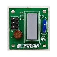
RDK-252
Description
KIT REF DESIGN DG CAPZERO
Manufacturer
Power Integrations
Series
CAPZero™r
Type
Other Power Managementr
Specifications of RDK-252
Main Purpose
Automatic X Capacitor Discharge
Embedded
No
Utilized Ic / Part
CAP014DG, CAP002DG, CAP012DG
Primary Attributes
Low No-Load Input Power (
Secondary Attributes
Surge Testing to EN6100-4-5 Class 4
Input Voltage
85 V to 264 V
Board Size
38.1 mm x 25.4 mm
Product
Power Management Modules
Dimensions
38.1 mm x 25.4 mm
Lead Free Status / RoHS Status
Lead free / RoHS Compliant
For Use With/related Products
CAP014DG
Other names
596-1313
Available stocks
Company
Part Number
Manufacturer
Quantity
Price
Company:

Part Number:
RDK-252
Manufacturer:
Power Integrations
Quantity:
135


Table 5 provides a list of commonly available cores and power
levels at which these cores can be used for typical designs.
Safety Margin, M (mm)
For designs that require safety isolation between primary and
secondary but do not use triple-insulated wire, the width of the
safety margin to be used on each side of the bobbin should be
entered here. For universal input designs, a total windings
margin of 6.2 mm would be required, and a value of 3.1 mm
would be entered into the spreadsheet. For vertical bobbins the
margin may not be symmetrical. However, if a total margin of
6.2 mm were required, then 3.1 mm would still be entered even
if the physical margin were only on one side of the bobbin.
For designs using triple insulated wire, it may still be necessary
to enter a small margin in order to meet the required safety
creepage distances. Typically, many bobbins exist for any core
size and, each will have different mechanical spacing. Refer to
the bobbin data sheet or seek guidance from your safety expert
or transformer vendor to determine what specific margin is
required.
As the margin reduces the available area for the windings, the
margin format described above may not be suitable for small
core sizes. If after entering the margin, more than 3 primary
layers (L) are required, it is suggested that either a larger core be
selected or switch to a zero margin design approach using
triple-insulated wire.
Primary Layers, L
Primary layers should be in the range of 1 < L < 3, and in
general it should be the lowest number that meets the primary
current density limit (CMA). Values of 100 Cmils/Amp for
designs <5 W scaling linearly to 500 Cmils/Amp at 200 W are
typical in designs without forced air cooling. Designs with more
than 3 layers are possible, but the increased leakage inductance
and issues associated with the physical fit of the windings
should be considered. A split primary construction may be
helpful for designs where leakage inductance clamp dissipation
is too high. Here half of the primary winding is placed on either
side of the secondary (and bias) winding in a sandwich
arrangement.
Secondary Turns, NS
If the grey override cell is left blank, the minimum number of
secondary turns is calculated such that the maximum operating
flux density B
3000 Gauss (300 mT). In general, it is not necessary to enter a
number in the override cell except in designs where a lower
operating flux density is desired (see the explanation of B
Step 5 – Iterate Transformer Design / Generate
Prototype
Iterate the design making sure that no warnings are displayed.
Any parameters outside the recommended range of values can
be corrected by following the guidance given in the right hand
column.
www.powerint.com
AN-47
M
is kept below the recommended maximum of
M
limits).
Once all warnings have been cleared, the output transformer
design parameters can be used to wind a prototype transformer
or sent to a vendor for samples. (See note on transformer
prototyping services in Quick Start section.)
The key transformer electrical parameters are:
Primary Inductance, L
This is the target nominal primary inductance of the transformer.
Primary Inductance Tolerance, LP
This is the assumed primary inductance tolerance. A value of
10% is used by default; however if specific information is known
from the transformer vendor, then this may be entered in the
grey override cell.
Number of Primary Turns, N
For low leakage inductance applications, a split primary
construction may be used, and is recommended for designs
above 20 W.
Gapped Core Effective Inductance, A
Used by the transformer vendor to specify the core center leg
air gap.
Maximum Operating Flux Density, B
A maximum value of 3000 Gauss during normal operation is
recommended. This limits transformer core loss and audible
noise generated at light load levels. This limit also prevents core
saturation during start-up or output short circuit. Under these
conditions the output voltage is low and little reset of the
transformer core occurs during the MOSFET off time. This
typically allows the transformer flux density to increase during
the next and subsequent cycles (staircasing) until the core
saturates. A value of 3000 Gauss at the peak current limit of
the selected device, together with the built in protection features
of TOPSwitch-JX, provides sufficient margin to prevent core
saturation under start-up or output short circuit conditions.
The multi-cycle modulation (MCM) mode of operation used in
TOPSwitch-JX can generate audio frequency components in
the transformer, especially if a long core is used. This audible
noise generation is minimized when a value of 3000 Gauss is
used for B
Gauss in MCM mode. Following this guideline and using the
standard transformer production technique of dip varnishing
practically eliminates audible noise. A careful evaluation of the
audible noise performance should be made using production
transformer samples before approving the design. Ceramic
capacitors that use dielectrics, such as Z5U, when used in
clamp circuits may also generate audio noise. If this is the
case, a solution may be to replace them with capacitors having
a different dielectric, for example a polyester film type.
Peak Flux Density, B
A maximum value of 4200 Gauss is recommended to limit the
maximum flux density under start-up and output short circuit
conditions. This calculation assumes worst-case current limit
and inductance values. In high ambient temperature applications,
M
. This results in an operating flux density of 750
P
(Gauss)
P
(µH)
P
Application Note
(TOLERANCE)
M
LG
(Gauss)
: (nH/T
(%)
2
)
Rev. A 030910
9
Related parts for RDK-252
Image
Part Number
Description
Manufacturer
Datasheet
Request
R

Part Number:
Description:
KIT REF DESIGN TOP HX FOR TOP258
Manufacturer:
Power Integrations
Datasheet:

Part Number:
Description:
KIT REF DESIGN LINKSWITCH 2
Manufacturer:
Power Integrations
Datasheet:

Part Number:
Description:
KIT REF DESIGN 1.2W PS TN FAMILY
Manufacturer:
Power Integrations
Datasheet:

Part Number:
Description:
KIT REF DESIGN 36-72W MOTOR DRVR
Manufacturer:
Power Integrations
Datasheet:

Part Number:
Description:
KIT REF DESIGN FOR LNK457D
Manufacturer:
Power Integrations
Datasheet:

Part Number:
Description:
REFERENCE DESIGN LINKSWITCH-PH
Manufacturer:
Power Integrations
Datasheet:

Part Number:
Description:
Specifications: Manufacturer: Power Integrations ; Output Voltage: 380 VDC ; Input / Supply Voltage (Max): 264 VAC ; Input / Supply Voltage (Min): 90 VAC ; Mounting Style: Through Hole ; Output Current: 0.913 A ; Output Power: 347 W
Manufacturer:
Power Integrations, Inc.

Part Number:
Description:
Power Management Modules & Development Tools TOPSwitch-JX REF. DESIGN KIT
Manufacturer:
Power Integrations
Datasheet:
Part Number:
Description:
Power Management IC Development Tools REF DESIGN RDR-292 PFF LED STREET LIGHT
Manufacturer:
Power Integrations

Part Number:
Description:
KIT REF DESIGN FOR LNK403EG
Manufacturer:
Power Integrations
Datasheet:

Part Number:
Description:
KIT REF DESIGN FOR LNK406EG
Manufacturer:
Power Integrations
Datasheet:

Part Number:
Description:
KIT REF DESIGN LINKSWITCH-CV
Manufacturer:
Power Integrations
Datasheet:

Part Number:
Description:
KIT REF DESIGN PFS762HG
Manufacturer:
Power Integrations
Datasheet:
Part Number:
Description:
Specifications: Family: Eval Boards - DC/DC & AC/DC (Off-Line) SMPS ; Series: HiperLCS™ ; Main Purpose: DC/DC, Step Down ; Outputs and Type: 1, Isolated ; Power - Output: 150W ; Voltage - Output: 24V ; Current - Output: 6.25A ; Voltage - Input:
Manufacturer:
Power Integrations, Inc.
Datasheet:

Part Number:
Description:
KIT REFERENCE DESIGN W/TN376PN
Manufacturer:
Power Integrations
Datasheet: