RDK-252 Power Integrations, RDK-252 Datasheet - Page 10
RDK-252
Manufacturer Part Number
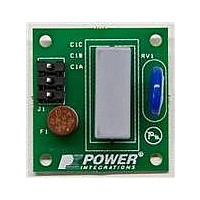
RDK-252
Description
KIT REF DESIGN DG CAPZERO
Manufacturer
Power Integrations
Series
CAPZero™r
Type
Other Power Managementr
Specifications of RDK-252
Main Purpose
Automatic X Capacitor Discharge
Embedded
No
Utilized Ic / Part
CAP014DG, CAP002DG, CAP012DG
Primary Attributes
Low No-Load Input Power (
Secondary Attributes
Surge Testing to EN6100-4-5 Class 4
Input Voltage
85 V to 264 V
Board Size
38.1 mm x 25.4 mm
Product
Power Management Modules
Dimensions
38.1 mm x 25.4 mm
Lead Free Status / RoHS Status
Lead free / RoHS Compliant
For Use With/related Products
CAP014DG
Other names
596-1313
Available stocks
Company
Part Number
Manufacturer
Quantity
Price
Company:

Part Number:
RDK-252
Manufacturer:
Power Integrations
Quantity:
135


such as sealed adapters or with lower grade ferrite core material,
this value may need to be reduced to 3600 Gauss due to the
higher operating ambient temperature. It is important to verify
that core saturation does not occur at maximum ambient tempera-
ture under overload conditions just prior to loss of regulation.
Maximum Primary Wire Diameter, OD (mm)
By default, if the override cell is empty, double insulated wire is
assumed and the standard wire diameter is chosen. The grey
override cells can be used to enter the wire diameter directly by
the user.
Rev. A 030910
Figure 10. Transformer Primary Design Parameters Section of Spreadsheet.
Figure 11. Transformer Secondary Design Parameters Section of Spreadsheet – Multiple Outputs.
TRANSFORMER PRIMARY DESIGN PARAMETERS
LP
LP Tolerance
NP
NB
ALG
BM
BP
BAC
ur
LG
BWE
OD
INS
DIA
AWG
CM
CMA
Primary Current Density (J)
TRANSFORMER SECONDARY DESIGN PARAMETERS (MULTIPLE OUTPUTS)
1st output
VO1
IO1_AVG
PO1_AVG
VD1
NS1
ISRMS1
IRIPPLE1
PIVS1
CMS1
AWGS1
DIAS1
ODS1
2nd output
VO2
IO2_AVG
PO2_AVG
VD2
NS2
ISRMS2
IRIPPLE2
PIVS2
CMS2
AWGS2
DIAS2
ODS2
3rd output
VO3
IO3_AVG
PO3_AVG
VD3
NS3
ISRMS3
IRIPPLE3
PIVS3
CMS3
AWGS3
DIAS3
ODS3
Total Continuous Output Power
Negative Output
10
Application Note
N/A
N/A
N/A
N/A
N/A
N/A
N/A
12.363 Amps
35.00 Watts
0.000 Amps
0.000 Amps
10.19 Amps
0.00 Watts
0.00 Watts
1435 uHenries
2637 Gauss
3603 Gauss
1918
2473 Cmils
0.38 mm
28.8 mm
0.39 mm
0.06 mm
0.33 mm
9.11 Amps/mm^2
7.00 Amps
3.00
1.29 mm
3.20 mm
0.38
0.00 Amps
0.38
0.00 Amps
265 nH/T^2
659 Gauss
161 Cmils
220 Cmils/Amp
0.5 Volts
0.7 Volts
0.7 Volts
10
74
28 AWG
20 Volts
16 AWG
35 Watts
7
5 Volts
2 Volts
0 Cmils
2 Volts
0 Cmils
Volts
Amps
AWG
mm
mm
Volts
Amps
AWG
mm
mm
The other factors automatically calculated by the spreadsheet
include:
Estimated Total Insulation Thickness, INS (mm)
Primary wire size, DIA: (mm)
Primary wire gauge, AWG
Number of primary layers, L
Estimated core center leg gap length: L
Number of secondary turns, N
Secondary wire size, DIAs: (mm)
Secondary wire gauge, AWG
Primary Inductance
Tolerance of Primary Inductance
Primary Winding Number of Turns
Bias Winding Number of Turns
Gapped Core Effective Inductance
Maximum Flux Density at PO, VMIN (BM<3000)
Peak Flux Density (BP<4200) at ILIMITMAX and LP_MAX. Note: Recommended values for adapters
and external power supplies <=3600 Gauss
AC Flux Density for Core Loss Curves (0.5 X Peak to Peak)
Relative Permeability of Ungapped Core
Gap Length (Lg > 0.1 mm)
Effective Bobbin Width
Maximum Primary Wire Diameter including insulation
Estimated Total Insulation Thickness (= 2 * film thickness)
Bare conductor diameter
Primary Wire Gauge (Rounded to next smaller standard AWG value)
Bare conductor effective area in circular mils
Primary Winding Current Capacity (200 < CMA < 500)
Primary Winding Current density (3.8 < J < 9.75)
Output Voltage
Average DC Output Current
Average Output Power
Output Diode Forward Voltage Drop
Output Winding Number of Turns
Output Winding RMS Current
Output Capacitor RMS Ripple Current
Output Rectifier Maximum Peak Inverse Voltage
Output Winding Bare Conductor minimum circular mils
Wire Gauge (Rounded up to next larger standard AWG value)
Minimum Bare Conductor Diameter
Maximum Outside Diameter for Triple Insulated Wire
Total Continuous Output Power
If negative output exists enter Output number; eg: If VO2 is negative output, enter 2
S
G
: (mm)
www.powerint.com
AN-47
Related parts for RDK-252
Image
Part Number
Description
Manufacturer
Datasheet
Request
R

Part Number:
Description:
KIT REF DESIGN TOP HX FOR TOP258
Manufacturer:
Power Integrations
Datasheet:

Part Number:
Description:
KIT REF DESIGN LINKSWITCH 2
Manufacturer:
Power Integrations
Datasheet:

Part Number:
Description:
KIT REF DESIGN 1.2W PS TN FAMILY
Manufacturer:
Power Integrations
Datasheet:

Part Number:
Description:
KIT REF DESIGN 36-72W MOTOR DRVR
Manufacturer:
Power Integrations
Datasheet:

Part Number:
Description:
KIT REF DESIGN FOR LNK457D
Manufacturer:
Power Integrations
Datasheet:

Part Number:
Description:
REFERENCE DESIGN LINKSWITCH-PH
Manufacturer:
Power Integrations
Datasheet:

Part Number:
Description:
Specifications: Manufacturer: Power Integrations ; Output Voltage: 380 VDC ; Input / Supply Voltage (Max): 264 VAC ; Input / Supply Voltage (Min): 90 VAC ; Mounting Style: Through Hole ; Output Current: 0.913 A ; Output Power: 347 W
Manufacturer:
Power Integrations, Inc.

Part Number:
Description:
Power Management Modules & Development Tools TOPSwitch-JX REF. DESIGN KIT
Manufacturer:
Power Integrations
Datasheet:
Part Number:
Description:
Power Management IC Development Tools REF DESIGN RDR-292 PFF LED STREET LIGHT
Manufacturer:
Power Integrations

Part Number:
Description:
KIT REF DESIGN FOR LNK403EG
Manufacturer:
Power Integrations
Datasheet:

Part Number:
Description:
KIT REF DESIGN FOR LNK406EG
Manufacturer:
Power Integrations
Datasheet:

Part Number:
Description:
KIT REF DESIGN LINKSWITCH-CV
Manufacturer:
Power Integrations
Datasheet:

Part Number:
Description:
KIT REF DESIGN PFS762HG
Manufacturer:
Power Integrations
Datasheet:
Part Number:
Description:
Specifications: Family: Eval Boards - DC/DC & AC/DC (Off-Line) SMPS ; Series: HiperLCS™ ; Main Purpose: DC/DC, Step Down ; Outputs and Type: 1, Isolated ; Power - Output: 150W ; Voltage - Output: 24V ; Current - Output: 6.25A ; Voltage - Input:
Manufacturer:
Power Integrations, Inc.
Datasheet:

Part Number:
Description:
KIT REFERENCE DESIGN W/TN376PN
Manufacturer:
Power Integrations
Datasheet: