RDK-252 Power Integrations, RDK-252 Datasheet - Page 20
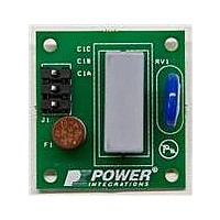
RDK-252
Manufacturer Part Number
RDK-252
Description
KIT REF DESIGN DG CAPZERO
Manufacturer
Power Integrations
Series
CAPZero™r
Type
Other Power Managementr
Specifications of RDK-252
Main Purpose
Automatic X Capacitor Discharge
Embedded
No
Utilized Ic / Part
CAP014DG, CAP002DG, CAP012DG
Primary Attributes
Low No-Load Input Power (
Secondary Attributes
Surge Testing to EN6100-4-5 Class 4
Input Voltage
85 V to 264 V
Board Size
38.1 mm x 25.4 mm
Product
Power Management Modules
Dimensions
38.1 mm x 25.4 mm
Lead Free Status / RoHS Status
Lead free / RoHS Compliant
For Use With/related Products
CAP014DG
Other names
596-1313
Available stocks
Company
Part Number
Manufacturer
Quantity
Price
Company:

Part Number:
RDK-252
Manufacturer:
Power Integrations
Quantity:
135


Figure 25. Correct Power Meter Configurations for Accurate Measurement of Low Power / No-load and Higher Power Designs.
Rev. A 030910
No-load Input Power Settling Time
When measuring input power under no-load or standby conditions
ensure an adequate measurement time to allow the input power
to stabilize. Figure 27 shows the typical settling time for a
no-load input power measurement of a TOPSwitch-JX design at
230 VAC input. Input power measurements were taken using a
Yokogawa WT210 power meter every 100 ms for 5.5 minutes
(330 s). Note that a delay of >90 s is needed to obtain a power
measurement within 3 mW (5%) of the final value (55.4 mW).
No-load Input Power Repeatability
TOPSwitch-JX has minimal no-load input power and light load
efficiency variability which reduces the design margin needed to
meet a given specification. Figure 26 shows an example of
typical performance. Here the no-load of a single power supply
was measured with 48 TOP266EG parts at a device
temperature of both 25 °C and 100 °C. The total spread at a
single temperature was <5 mW and <7 mW including data from
both temperatures.
Figure 26. Example of Device to Device and Temperature Variation on No-load Input Power Measured in a Single Power Supply.
20
Application Note
V
(a) Low Power (<100 W) and No-load Power Input
Configuration (a) is Recommended for TOPSwitch-JX Power Levels.
IN
Power Measurements
V
Power Meter
2 MΩ
A
16 mΩ
PSU
Improving Light Load Efficiency and No-load Input Power
During light load and no-load conditions the consumption of the
feedback network, line sensing resistors and clamp are
significant and without optimization can double the no-load
input power of a design or significantly reduce available output
power under standby conditions.
The following approaches can be followed to minimize these
losses
•
•
•
•
•
•
•
However before trying these techniques first verify that the
power meter used to make input power measurements is
correctly configured (Figure 25).
Minimize output pre-loads
Connect line sense resistor to V pin
Clamp choice and optimization
Minimize bias winding voltage
Increase value of line sense resistance
Configure optocoupler transistor as part of Darlington pair
Use of TLV431 vs. TL431 secondary reference IC
V
IN
(b) High Power (>100 W)
A
16 mΩ
Power Meter
2 MΩ
V
www.powerint.com
PI-5848-030910
PSU
AN-47
Related parts for RDK-252
Image
Part Number
Description
Manufacturer
Datasheet
Request
R

Part Number:
Description:
KIT REF DESIGN TOP HX FOR TOP258
Manufacturer:
Power Integrations
Datasheet:

Part Number:
Description:
KIT REF DESIGN LINKSWITCH 2
Manufacturer:
Power Integrations
Datasheet:

Part Number:
Description:
KIT REF DESIGN 1.2W PS TN FAMILY
Manufacturer:
Power Integrations
Datasheet:

Part Number:
Description:
KIT REF DESIGN 36-72W MOTOR DRVR
Manufacturer:
Power Integrations
Datasheet:

Part Number:
Description:
KIT REF DESIGN FOR LNK457D
Manufacturer:
Power Integrations
Datasheet:

Part Number:
Description:
REFERENCE DESIGN LINKSWITCH-PH
Manufacturer:
Power Integrations
Datasheet:

Part Number:
Description:
Specifications: Manufacturer: Power Integrations ; Output Voltage: 380 VDC ; Input / Supply Voltage (Max): 264 VAC ; Input / Supply Voltage (Min): 90 VAC ; Mounting Style: Through Hole ; Output Current: 0.913 A ; Output Power: 347 W
Manufacturer:
Power Integrations, Inc.

Part Number:
Description:
Power Management Modules & Development Tools TOPSwitch-JX REF. DESIGN KIT
Manufacturer:
Power Integrations
Datasheet:
Part Number:
Description:
Power Management IC Development Tools REF DESIGN RDR-292 PFF LED STREET LIGHT
Manufacturer:
Power Integrations

Part Number:
Description:
KIT REF DESIGN FOR LNK403EG
Manufacturer:
Power Integrations
Datasheet:

Part Number:
Description:
KIT REF DESIGN FOR LNK406EG
Manufacturer:
Power Integrations
Datasheet:

Part Number:
Description:
KIT REF DESIGN LINKSWITCH-CV
Manufacturer:
Power Integrations
Datasheet:

Part Number:
Description:
KIT REF DESIGN PFS762HG
Manufacturer:
Power Integrations
Datasheet:
Part Number:
Description:
Specifications: Family: Eval Boards - DC/DC & AC/DC (Off-Line) SMPS ; Series: HiperLCS™ ; Main Purpose: DC/DC, Step Down ; Outputs and Type: 1, Isolated ; Power - Output: 150W ; Voltage - Output: 24V ; Current - Output: 6.25A ; Voltage - Input:
Manufacturer:
Power Integrations, Inc.
Datasheet:

Part Number:
Description:
KIT REFERENCE DESIGN W/TN376PN
Manufacturer:
Power Integrations
Datasheet: