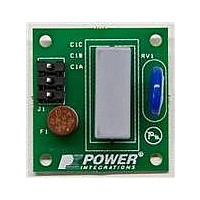
RDK-252 Power Integrations, RDK-252 Datasheet - Page 8

RDK-252
Manufacturer Part Number
RDK-252
Description
KIT REF DESIGN DG CAPZERO
Manufacturer
Power Integrations
Series
CAPZero™r
Type
Other Power Managementr
Specifications of RDK-252
Main Purpose
Automatic X Capacitor Discharge
Embedded
No
Utilized Ic / Part
CAP014DG, CAP002DG, CAP012DG
Primary Attributes
Low No-Load Input Power (
Secondary Attributes
Surge Testing to EN6100-4-5 Class 4
Input Voltage
85 V to 264 V
Board Size
38.1 mm x 25.4 mm
Product
Power Management Modules
Dimensions
38.1 mm x 25.4 mm
Lead Free Status / RoHS Status
Lead free / RoHS Compliant
For Use With/related Products
CAP014DG
Other names
596-1313
Available stocks
Company
Part Number
Manufacturer
Quantity
Price
Company:
Part Number:
RDK-252
Manufacturer:
Power Integrations
Quantity:
135
Figure 9. Transformer Core and Construction Variables Section of Spreadsheet.
Output Power Limiting vs. Input Voltage (Optional)
The X pin on the TOPSwitch-JX can be used to program a
current limit value lower than the maximum internal current limit
for the part selected. A resistor connected from the X pin to the
SOURCE pin (R
programmed current limit. See data sheet for current limit
resistor selection curves.
The addition of a second resistor connected from the X pin to
the DC-Bus (R
programmed current limit as a function of the line voltage. This
is desirable as typical flyback power supplies that operate in
continuous conduction mode at low line (K
higher overload power capability at high line by 200-300%. In
certain applications this may require over design of the output
diode, transformer and output capacitors to handle the
increased dissipation during an overload fault.
The PIXls spreadsheet calculates the values of the two resistors
required for power limiting vs. line based on the choice of the
TOPSwitch-JX part and the value of K
target current limit value is equal to I
target current limit value is calculated based on the value
required for specified P
overload current limit ratio at V
120% ensures that the MOSFET protection mode is not
triggered during start-up, especially with high output voltage
designs. Lower values are acceptable, but start-up into
maximum (peak) load at high input line voltage must be verified.
Resistor values are calculated using the worst case current limit
reduction curves provided in the TOPSwitch-JX data sheet.
Step 4 – Choose Core and Bobbin Based on Output
Power and Enter A
Core effective cross-sectional area, A
Core effective path length, L
Core ungapped effective inductance, A
Bobbin width, BW: (mm)
Tape margin width equal to half the total margin, M (mm)
Primary Layers, L
Secondary Turns, N
Core Type
If the core type cell is left empty, the spreadsheet will default to
the smallest commonly available core suitable for the continuous
(average) output power specified. The entire list of cores
available can be selected from the drop down list in the tool bar
of the PIXls design software.
Rev. A 030910
AL
BW
M
L
NS
ENTER TRANSFORMER CORE/CONSTRUCTION VARIABLES
Core Type
Core
Bobbin
AE
LE
8
Application Note
PL
IL
), as shown in Figure 12, allows reduction of the
in Figure 1) allows selection of a fixed externally
S
E
, L
O(PEAK)
E
, A
L
E
multiplied by the margin factor,
, BW, M, L, N
: (cm).
MAX
. The recommended value of
LIMIT(MIN_EXT)
E
P
: (cm
L
selected. At V
: (nH/turn
P
2
S
Auto
)
<1) will have a
0.00
3.00
. At high line the
EI28_BOBBIN
2
).
EI28
MIN
EI28
the
4300 nH/T^2
0.86 cm^2
4.82 cm
9.6 mm
3
P/N:
P/N:
mm
The grey override cells can be used to enter the core and
bobbin parameters directly. This is useful if a core is selected
that is not on the list, or the specific core or bobbin information
differs from that referenced by the spreadsheet.
Table 5. Transformer Core Table.
0 - 10 W
100 W -
>150 W
Output
10 W -
20 W -
30 W -
50 W -
70 W -
Power
100 W
150 W
20 W
30 W
50 W
70 W
Safety Margin Width (Half the Primary to Secondary Creepage Distance)
Number of Primary Layers
Number of Secondary Turns
Core Type
PC40EI28-Z
BE-28-1110CPL
Core Effective Cross Sectional Area
Core Effective Path Length
Ungapped Core Effective Inductance
Bobbin Physical Winding Width
E36/18/11
E42/21/15
E42/21/20
E55/28/21
EI22/19/6
E30/15/7
Insulated
EF12.6
EER28
ETD29
ETD34
ETD39
EER40
EE13
EE16
EE19
Triple
EF16
EF20
EF25
EF32
Wire
EI22
EI28
EI30
EI35
EI40
66 kHz
E36/18/11
E42/21/15
E42/21/20
E55/28/21
EI22/19/6
E30/15/7
EI33/29/
EER28L
Wound
EPC30
EER28
EER35
EER40
Margin
EEL16
EEL19
EEL22
EEL25
ETD29
ETD34
ETD39
EE19
EF20
EF25
EF32
13-Z
EI22
EI25
EI28
EI30
EI35
EI40
E36/18/11
E42/21/15
E42/21/20
E55/28/21
EI22/19/6
E30/15/7
Insulated
EF12.6
EER28
ETD29
ETD34
ETD39
EER40
EE13
EE16
EE19
Triple
EF16
EF20
EF25
EF32
Wire
EI22
EI28
EI30
EI35
EI40
www.powerint.com
132 kHz
E36/18/11
E42/21/15
E42/21/20
E55/28/21
EI22/19/6
E30/15/7
EI33/29/
EER28L
Wound
Margin
EER28
ETD29
ETD34
EER35
ETD39
EER40
EEL16
EEL19
EEL22
EEL25
EE19
EF20
EF32
AN-47
13-Z
EI22
EI25
EI28
EI35
EI40


