RDK-252 Power Integrations, RDK-252 Datasheet - Page 3
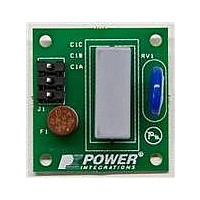
RDK-252
Manufacturer Part Number
RDK-252
Description
KIT REF DESIGN DG CAPZERO
Manufacturer
Power Integrations
Series
CAPZero™r
Type
Other Power Managementr
Specifications of RDK-252
Main Purpose
Automatic X Capacitor Discharge
Embedded
No
Utilized Ic / Part
CAP014DG, CAP002DG, CAP012DG
Primary Attributes
Low No-Load Input Power (
Secondary Attributes
Surge Testing to EN6100-4-5 Class 4
Input Voltage
85 V to 264 V
Board Size
38.1 mm x 25.4 mm
Product
Power Management Modules
Dimensions
38.1 mm x 25.4 mm
Lead Free Status / RoHS Status
Lead free / RoHS Compliant
For Use With/related Products
CAP014DG
Other names
596-1313
Available stocks
Company
Part Number
Manufacturer
Quantity
Price
Company:

Part Number:
RDK-252
Manufacturer:
Power Integrations
Quantity:
135


Step-by-Step Transformer Design
Procedure Introduction
The design flow allows for design of power supplies both with or
without a peak output power requirement. For peak power
requirements the device current limit is programmed to enable
the delivery of peak power for a short duration limited only by
thermal characteristics of the TOPSwitch-JX package and
ratings of other components in the circuit.
As average power increases, based on the measured trans-
former and device temperature, it may be necessary to select a
larger transformer to allow increased copper area for the
windings and/or to increase the amount of device heatsinking.
The power table (Table 1) provides guidance for peak and
continuous (average) power levels obtainable in both sealed
adapter and open frame applications. For the V package without
an external heatsink, the power values for adapter and open
frame are thermally limited. The peak values represent the
electrically limited output power, assuming operation at current
limit (I
also thermally limited, however, the open frame values are
electrically limited and therefore also represent the peak output
power. As the continuous power values are thermally limited,
they indicate the upper limit of continuous power for worst case
conditions but may vary depending on the specific application.
For example, if the peak power condition has a very low duty
cycle, such as the 1-second peak required to close the drawer in
a DVD player, then the thermal rise of the device (and transformer)
is only a function of the continuous average power. However, if
the peak power is repetitive with a significant duty cycle, then it
would need to be considered as a limiting factor in the design.
Figure 2 shows how to calculate the average power requirements
for a design with two different peak load conditions.
Where P
durations of each peak power condition and T is the period of
one cycle of the pulsed load condition.
The design procedure requires both peak and continuous
(average) powers to be specified. If there is no peak power
requirement for the design, the same value should be used for
both continuous and peak power.
Figure 3. Application Variable Section of TOPSwitch-JX Design Spreadsheet.
www.powerint.com
ENTER APPLICATION VARIABLES
VACMIN
VACMAX
fL
VO
PO_AVG
PO_PEAK
Heatsink Type
Enclosure
n
Z
VB
tC
CIN
AN-47
LIM(MIN)
d
P
1
X
AVE
=
are the different output power conditions, Dt
). For the E package, the adapter power values are
= P
Dt
T
1
, d
1
+ P
2
=
]
Dt
3
T
- P
2
1
g # d
1
+ P
]
External
Adapter
2
35.00
5.00
0.80
0.50
3.00
68.0
- P
265
85
50
12
1
g # d
X
2
External
are the
35.00 Watts
68 uFarads
Volts
Volts
Hertz
Volts
Watts
%/100
Volts
ms
Power (W)
The peak power is used to select the TOPSwitch-JX device and
design the transformer for power delivery at minimum input line
voltage while continuous (or average power if the peak load is
periodic) is used for thermal design and may affect the size of
the transformer and the heatsink.
Step 1. Enter Application Variables VAC
P
Determine the input voltage range from Table 2.
Table 2. Standard Worldwide Input Line Voltage Ranges.
Line Frequency, f
50 Hz for universal or single 100 VAC, 60 Hz for single 115 VAC
input. 50 Hz for single 230 VAC input. These values represent
typical line frequencies rather than minimums. For most
applications this gives adequate overall design margin. For
absolute worst case or based on the product specification,
reduce these numbers by 6% (47 Hz or 56 Hz). For half-wave
rectification, use f
into Cells B67 and B68.
Figure 2. Continuous (average) Output Power Calculation Example.
100/115
230
Universal
P
P
P
O(AVE)
Nominal Input Voltage (VAC)
3
2
1
Design title
Minimum AC Input Voltage
Maximum AC Input Voltage
AC Mains Frequency
Output Voltage (main)
Average Output Power
Peak Output Power
Heatsink Type
Open Frame enclosure assume sufficienct airflow while adapter means a sealed enclosure.
Efficiency Estimate
Loss Allocation Factor
Bias Voltage - Verify that VB is > 8 V at no load and VMAX
Bridge Rectifier Conduction Time Estimate
Input Filter Capacitor
, P
O(PEAK)
, h, Z, V
∆t
L
/2. For DC input, enter the voltage directly
L
1
B
, t
C
, C
IN
Application Note
T
VAC
195
85
85
∆t
MIN
2
MIN
, VAC
VAC
MAX
132
265
265
Rev. A 030910
, f
MAX
Time (t)
L
, V
3
O
,
Related parts for RDK-252
Image
Part Number
Description
Manufacturer
Datasheet
Request
R

Part Number:
Description:
KIT REF DESIGN TOP HX FOR TOP258
Manufacturer:
Power Integrations
Datasheet:

Part Number:
Description:
KIT REF DESIGN LINKSWITCH 2
Manufacturer:
Power Integrations
Datasheet:

Part Number:
Description:
KIT REF DESIGN 1.2W PS TN FAMILY
Manufacturer:
Power Integrations
Datasheet:

Part Number:
Description:
KIT REF DESIGN 36-72W MOTOR DRVR
Manufacturer:
Power Integrations
Datasheet:

Part Number:
Description:
KIT REF DESIGN FOR LNK457D
Manufacturer:
Power Integrations
Datasheet:

Part Number:
Description:
REFERENCE DESIGN LINKSWITCH-PH
Manufacturer:
Power Integrations
Datasheet:

Part Number:
Description:
Specifications: Manufacturer: Power Integrations ; Output Voltage: 380 VDC ; Input / Supply Voltage (Max): 264 VAC ; Input / Supply Voltage (Min): 90 VAC ; Mounting Style: Through Hole ; Output Current: 0.913 A ; Output Power: 347 W
Manufacturer:
Power Integrations, Inc.

Part Number:
Description:
Power Management Modules & Development Tools TOPSwitch-JX REF. DESIGN KIT
Manufacturer:
Power Integrations
Datasheet:
Part Number:
Description:
Power Management IC Development Tools REF DESIGN RDR-292 PFF LED STREET LIGHT
Manufacturer:
Power Integrations

Part Number:
Description:
KIT REF DESIGN FOR LNK403EG
Manufacturer:
Power Integrations
Datasheet:

Part Number:
Description:
KIT REF DESIGN FOR LNK406EG
Manufacturer:
Power Integrations
Datasheet:

Part Number:
Description:
KIT REF DESIGN LINKSWITCH-CV
Manufacturer:
Power Integrations
Datasheet:

Part Number:
Description:
KIT REF DESIGN PFS762HG
Manufacturer:
Power Integrations
Datasheet:
Part Number:
Description:
Specifications: Family: Eval Boards - DC/DC & AC/DC (Off-Line) SMPS ; Series: HiperLCS™ ; Main Purpose: DC/DC, Step Down ; Outputs and Type: 1, Isolated ; Power - Output: 150W ; Voltage - Output: 24V ; Current - Output: 6.25A ; Voltage - Input:
Manufacturer:
Power Integrations, Inc.
Datasheet:

Part Number:
Description:
KIT REFERENCE DESIGN W/TN376PN
Manufacturer:
Power Integrations
Datasheet: