RDK-252 Power Integrations, RDK-252 Datasheet - Page 14
RDK-252
Manufacturer Part Number
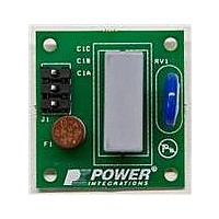
RDK-252
Description
KIT REF DESIGN DG CAPZERO
Manufacturer
Power Integrations
Series
CAPZero™r
Type
Other Power Managementr
Specifications of RDK-252
Main Purpose
Automatic X Capacitor Discharge
Embedded
No
Utilized Ic / Part
CAP014DG, CAP002DG, CAP012DG
Primary Attributes
Low No-Load Input Power (
Secondary Attributes
Surge Testing to EN6100-4-5 Class 4
Input Voltage
85 V to 264 V
Board Size
38.1 mm x 25.4 mm
Product
Power Management Modules
Dimensions
38.1 mm x 25.4 mm
Lead Free Status / RoHS Status
Lead free / RoHS Compliant
For Use With/related Products
CAP014DG
Other names
596-1313
Available stocks
Company
Part Number
Manufacturer
Quantity
Price
Company:

Part Number:
RDK-252
Manufacturer:
Power Integrations
Quantity:
135


Rev. A 030910
The peak drain voltage should be limited to a maximum of 675 V
under these conditions to provide a margin for component
variation. The clamp diode (D
fast recovery type with a reverse recovery time <500 ns. Under
no circumstances should a standard recovery rectifier diode be
used. The high dissipation that may result during start-up or an
output short circuit can cause failure of the diode. Resistor
R
different members of the TOPSwitch-JX family will have different
peak primary currents and leakage inductances, and therefore
different leakage energy. Capacitor C
optimized for each design. As a general rule, minimize the value
of capacitor C
while still meeting the recommended 675 V peak drain voltage
limit.
Step 9 – Select Output Rectifier Diode
For each output use the values of peak inverse voltage (V
output current (I
the output diodes. Table 6 shows some commonly available
types.
V
Parameters section of the spreadsheet and Transformer
Secondary Design Parameters (Multiple Outputs).
I
average output current. Depending on the temperature rise and
the duration of the peak load condition, it may be necessary to
increase the diode current rating once a prototype has been
built. This also applies to the amount of heatsinking required.
Step 10 – Select Output Capacitor
Ripple Current Rating
The spreadsheet calculates output capacitor ripple current using
the average output power. Therefore the actual rating of the
capacitor will depend on the peak to average power ratio of the
design. In most cases this assumption will be valid as capacitor
ripple rating is a thermal limitation, and most peak load durations
are shorter than the thermal time constant of the capacitor (<1s).
For such designs, select the output capacitor(s) such that the
ripple rating is greater than the calculated value of I
spreadsheet. However, in designs with high peak to continuous
(average) power and long duration peak load conditions, the
capacitor rating may need to be increased based on the
measured capacitor temperature rise under worst-case load and
ambient conditions.
In either case, if a suitable individual capacitor cannot be found,
then two or more capacitors may be used in parallel to achieve a
combined ripple current rating equal to the sum of the individual
capacitor ratings.
Many capacitor manufacturers provide factors that increase the
ripple current rating as the capacitor operating temperature is
reduced from its data sheet maximum. This should also be
considered to ensure that the capacitor is not oversized.
D
R
CLAMP1
≥ 2 x I
14
≥ 1.25 x PIV
damps ringing for reduced EMI. Power supplies using
O
Application Note
: where I
CLAMP
S
: where PIV
O
) provided in the design spreadsheet to select
D
and maximize the value of resistor R
is the diode rated DC current, and I
S
is taken from the Voltage Stress
CLAMP
) must be a fast or an ultra-
CLAMP
and R
CLAMP
RIPPLE
must be
O
CLAMP
from the
is the
R
) and
ESR Specification
The switching ripple voltage on the output is equal to the peak
secondary current multiplied by the ESR of the output capacitor
(electrolytic types assumed). It is therefore important to select
low ESR capacitor types to reduce the ripple voltage. In
general, selecting a capacitor rated for the output ripple, will
result in an acceptable value of ESR.
Voltage Rating
Select a voltage rating such that V
Step 11 – Select Feedback Circuit Components
The choice of the feedback circuit for a power supply is
governed by the desired output regulation. A simple feedback
circuit can be configured using a Zener diode in series with the
optocoupler diode. Though this method is inexpensive, it relies
on the Zener diode to control the output voltage, which limits
performance due to the device’s wide tolerance and large
temperature coefficient as compared to a referenced IC.
Figure 14 shows a typical implementation of Zener feedback.
The drop across the Zener diode D
Table 7. Optocouplers.
PC123Y6
PC817X1
PC817X4J
SFH615A-2
SFH617A-2
SFH618A-2
ISP817A
LTV817A
LTV816A
LTV123A
LTV817D
K1010A
LTV702FB
LTV703FB
LTV713FA
K2010
PC702V2NSZX
PC703V2NSZX
PC713V1NSZX
PC714V1NSZX
MOC8102
MOC8103
MOC8105
CNY17F-2
P/N
4 Pin DIP
6 Pin DIP
CTR(%)
300-600
300-600
108-173
80-160
80-160
63-125
63-125
63-125
80-160
80-160
80-160
80-160
60-160
63-125
63-125
80-160
60-160
63-125
63-125
80-160
80-160
73-117
63-133
63-125
BVCEO
RATED
Z
, optocoupler series resistor
70 V
70 V
80 V
70 V
70 V
55 V
35 V
35 V
80 V
70 V
35 V
60 V
70 V
70 V
35 V
60 V
70 V
70 V
35 V
35 V
30 V
30 V
30 V
70 V
≥1.25 × V
www.powerint.com
Sharp
Sharp
Sharp
Vishay, Isocom
Vishay, Isocom
Vishay, Isocom
Vishay, Isocom
Liteon
Liteon
Liteon
Liteon
Cosmo
Liteon
Liteon
Liteon
Cosmo
Sharp
Sharp
Sharp
Sharp
Vishay, Isocom
Vishay, Isocom
Vishay, Isocom
Vishay, Isocom,
Liteon
O
Manufacturer
.
AN-47
Related parts for RDK-252
Image
Part Number
Description
Manufacturer
Datasheet
Request
R

Part Number:
Description:
KIT REF DESIGN TOP HX FOR TOP258
Manufacturer:
Power Integrations
Datasheet:

Part Number:
Description:
KIT REF DESIGN LINKSWITCH 2
Manufacturer:
Power Integrations
Datasheet:

Part Number:
Description:
KIT REF DESIGN 1.2W PS TN FAMILY
Manufacturer:
Power Integrations
Datasheet:

Part Number:
Description:
KIT REF DESIGN 36-72W MOTOR DRVR
Manufacturer:
Power Integrations
Datasheet:

Part Number:
Description:
KIT REF DESIGN FOR LNK457D
Manufacturer:
Power Integrations
Datasheet:

Part Number:
Description:
REFERENCE DESIGN LINKSWITCH-PH
Manufacturer:
Power Integrations
Datasheet:

Part Number:
Description:
Specifications: Manufacturer: Power Integrations ; Output Voltage: 380 VDC ; Input / Supply Voltage (Max): 264 VAC ; Input / Supply Voltage (Min): 90 VAC ; Mounting Style: Through Hole ; Output Current: 0.913 A ; Output Power: 347 W
Manufacturer:
Power Integrations, Inc.

Part Number:
Description:
Power Management Modules & Development Tools TOPSwitch-JX REF. DESIGN KIT
Manufacturer:
Power Integrations
Datasheet:
Part Number:
Description:
Power Management IC Development Tools REF DESIGN RDR-292 PFF LED STREET LIGHT
Manufacturer:
Power Integrations

Part Number:
Description:
KIT REF DESIGN FOR LNK403EG
Manufacturer:
Power Integrations
Datasheet:

Part Number:
Description:
KIT REF DESIGN FOR LNK406EG
Manufacturer:
Power Integrations
Datasheet:

Part Number:
Description:
KIT REF DESIGN LINKSWITCH-CV
Manufacturer:
Power Integrations
Datasheet:

Part Number:
Description:
KIT REF DESIGN PFS762HG
Manufacturer:
Power Integrations
Datasheet:
Part Number:
Description:
Specifications: Family: Eval Boards - DC/DC & AC/DC (Off-Line) SMPS ; Series: HiperLCS™ ; Main Purpose: DC/DC, Step Down ; Outputs and Type: 1, Isolated ; Power - Output: 150W ; Voltage - Output: 24V ; Current - Output: 6.25A ; Voltage - Input:
Manufacturer:
Power Integrations, Inc.
Datasheet:

Part Number:
Description:
KIT REFERENCE DESIGN W/TN376PN
Manufacturer:
Power Integrations
Datasheet: