RDK-252 Power Integrations, RDK-252 Datasheet - Page 17
RDK-252
Manufacturer Part Number
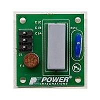
RDK-252
Description
KIT REF DESIGN DG CAPZERO
Manufacturer
Power Integrations
Series
CAPZero™r
Type
Other Power Managementr
Specifications of RDK-252
Main Purpose
Automatic X Capacitor Discharge
Embedded
No
Utilized Ic / Part
CAP014DG, CAP002DG, CAP012DG
Primary Attributes
Low No-Load Input Power (
Secondary Attributes
Surge Testing to EN6100-4-5 Class 4
Input Voltage
85 V to 264 V
Board Size
38.1 mm x 25.4 mm
Product
Power Management Modules
Dimensions
38.1 mm x 25.4 mm
Lead Free Status / RoHS Status
Lead free / RoHS Compliant
For Use With/related Products
CAP014DG
Other names
596-1313
Available stocks
Company
Part Number
Manufacturer
Quantity
Price
Company:

Part Number:
RDK-252
Manufacturer:
Power Integrations
Quantity:
135


R
Resistor R
diode is operating close to its knee voltage. Resistor R
the DC gain of the feedback. Both these can be 0.125 W or
0.25 W, 5% types. Selecting a Zener with a low test current
(l
bias the feedback network, reducing no-load input power
consumption.
For improved accuracy, Figure 15 shows a typical implementation
using a reference IC. A TL431 is used to set the output voltage
and is programmed via a resistor divider R
sets the DC gain. The presence of capacitor C
very near 0 Hz (practically limited by the finite gain of the TL431)
in the closed loop transfer function. Furthermore, C
with resistors R
The component values should be chosen such that this zero
occurs at approximately 100 Hz.
The 7 kHz internal pole from the TOPSwitch-JX provides the
high frequency pole (f
configuration (see Figure 16).
In certain cases an increase in phase (phase boost) may be
required near the crossover frequency. Once the desired
crossover frequency f
of resistor R
placed across R
starting values for these components are
This arrangement places a pole zero pair (f
typically provide about 30° of additional phase margin without
significantly alerting the crossover frequency f
A post filter (L
frequency switching noise and ripple. Inductor L
the range of 1 µH – 3.3 µH with a current rating above the peak
output current. Capacitor C
to 330 µF with a voltage rating ≥1.25 x V
L
occur at or slightly beyond 10 kHz. This is to ensure that there
is no phase degradation due to the post filter inside the bandwidth
of the power supply. If a post filter is used then the optocoupler
should be connected as shown, before the post filter inductor
and the sense resistors. Connecting after the post filter
typically causes oscillation.
Table 7 is a list of commonly used optocouplers for feedback
control of isolated switching power supplies. Use of an
optocoupler with a typical CTR of 1 to 6 is recommended.
www.powerint.com
ZT
PF
D
AN-47
and the optocoupler LED determine the output voltage.
≤5 mA) is recommended to minimize the current needed to
and C
PF
BIAS
should be such that their resonant frequency should
D
, an RC network (formed by R
PF
provides a 1 mA bias current so that the Zener
T
D
and C
and R
can provide this phase boost. Recommended
R
C
f
C
P1
Z
B
B
PF
S1
1
has been achieved through the selection
) to complete the type 2 compensation
.
.
=
) is typically added to reduce high
form a low frequency zero (f
R
10 2
2
9
D
r
PF
^
^
should be in the range of 100 µF
R
r
T
#
+
9
1
R
R C
B
S
1
#
h
OUT
f
S1
C
T
h
B
Z2
. The combination of
and R
and C
and f
C
T
(see Figure 17).
adds a pole
PF
S2
P2
B
should be in
. Resistor R
) can be
Z1
) which can
T
) located at
together
D
sets
D
Tips for Designs
Design Recommendations:
•
•
Circuit Board Layout
TOPSwitch-JX is a highly integrated power supply solution that
integrates on a single die both the controller and the high voltage
MOSFET. The presence of high switching currents and voltages
together with analog signals makes it especially important to
follow good PCB design practice to ensure stable and trouble
free operation of the power supply.
When designing a PCB for the TOPSwitch-JX based power
supply, it is important to follow the following guidelines:
Primary Side Connections
•
•
•
•
•
•
A soft finish circuit is recommended for high output voltage
designs (>12 V) especially where large value output capacitors
are used. This ensures start-up with full load at low line and
also prevent output voltage overshoot. In Figure 22, R23, D6
and C19 show one implementation of the soft finish circuit.
A 10 µF, 50 V electrolytic capacitor is recommended for the
bias winding output filter to ensure appropriate bias voltage for
the optocoupler when the power supply is unloaded. At high
line and no-load, the bias voltage should not drop below 7 V
(worst case) for best no-load input power performance.
Adjust bias winding voltage or capacitor accordingly.
Use a single point (Kelvin) connection at the negative terminal
of the input filter capacitor for the TOPSwitch-JX SOURCE pin
and bias winding return. This improves surge capabilities by
returning capacitive displacement currents that flow across
the isolation barrier directly to the input filter capacitor.
The CONTROL pin bypass capacitor should be located as
close as possible to the SOURCE and CONTROL pins and its
SOURCE connection trace should not be shared by the main
MOSFET switching currents or bias winding return connection.
All SOURCE pin referenced components connected to the
VOLTAGE MONITOR (V) or EXTERNAL CURRENT LIMIT (X)
pins should also be located closely between that pin and the
SOURCE pin. The SOURCE connection trace of these
components should not be shared by the main MOSFET
switching or bias winding return currents. It is very critical that
the SOURCE pin switching current is returned to the input
capacitor negative terminal through a separate trace that is
not shared by the components connected to CONTROL,
VOLTAGE-MONITOR or EXTERNAL CURRENT LIMIT pins.
This is because the SOURCE pin is also the controller ground
reference pin. Any traces to the V or X pins should be kept as
short as possible and physically away from the DRAIN node,
clamp components or any node with high di/dt or dv/dt, to
prevent noise coupling.
The line sense resistor should be located close to the V pin to
minimize the trace length on the high impedance V pin side.
The DC bus side of the V pin resistor should be connected as
close to the bulk capacitor as possible.
In addition to the 47 µF CONTROL pin capacitor, a high
frequency 0.1 µF bypass capacitor in parallel should be used
for local decoupling (C
The feedback optocoupler output should be routed away from
any high voltage or high current traces to prevent noise coupling.
BP
in Figure 18).
Application Note
Rev. A 030910
17
Related parts for RDK-252
Image
Part Number
Description
Manufacturer
Datasheet
Request
R

Part Number:
Description:
KIT REF DESIGN TOP HX FOR TOP258
Manufacturer:
Power Integrations
Datasheet:

Part Number:
Description:
KIT REF DESIGN LINKSWITCH 2
Manufacturer:
Power Integrations
Datasheet:

Part Number:
Description:
KIT REF DESIGN 1.2W PS TN FAMILY
Manufacturer:
Power Integrations
Datasheet:

Part Number:
Description:
KIT REF DESIGN 36-72W MOTOR DRVR
Manufacturer:
Power Integrations
Datasheet:

Part Number:
Description:
KIT REF DESIGN FOR LNK457D
Manufacturer:
Power Integrations
Datasheet:

Part Number:
Description:
REFERENCE DESIGN LINKSWITCH-PH
Manufacturer:
Power Integrations
Datasheet:

Part Number:
Description:
Specifications: Manufacturer: Power Integrations ; Output Voltage: 380 VDC ; Input / Supply Voltage (Max): 264 VAC ; Input / Supply Voltage (Min): 90 VAC ; Mounting Style: Through Hole ; Output Current: 0.913 A ; Output Power: 347 W
Manufacturer:
Power Integrations, Inc.

Part Number:
Description:
Power Management Modules & Development Tools TOPSwitch-JX REF. DESIGN KIT
Manufacturer:
Power Integrations
Datasheet:
Part Number:
Description:
Power Management IC Development Tools REF DESIGN RDR-292 PFF LED STREET LIGHT
Manufacturer:
Power Integrations

Part Number:
Description:
KIT REF DESIGN FOR LNK403EG
Manufacturer:
Power Integrations
Datasheet:

Part Number:
Description:
KIT REF DESIGN FOR LNK406EG
Manufacturer:
Power Integrations
Datasheet:

Part Number:
Description:
KIT REF DESIGN LINKSWITCH-CV
Manufacturer:
Power Integrations
Datasheet:

Part Number:
Description:
KIT REF DESIGN PFS762HG
Manufacturer:
Power Integrations
Datasheet:
Part Number:
Description:
Specifications: Family: Eval Boards - DC/DC & AC/DC (Off-Line) SMPS ; Series: HiperLCS™ ; Main Purpose: DC/DC, Step Down ; Outputs and Type: 1, Isolated ; Power - Output: 150W ; Voltage - Output: 24V ; Current - Output: 6.25A ; Voltage - Input:
Manufacturer:
Power Integrations, Inc.
Datasheet:

Part Number:
Description:
KIT REFERENCE DESIGN W/TN376PN
Manufacturer:
Power Integrations
Datasheet: